InfiLINK Evolution and InfiMAN Evolution - initial link configuration and installation
What’s in the box?
account course progress
Package content
Check the packing lists and make sure that the correct part numbers and quantities of goods have arrived. The standard components of an InfiLINK Evolution and InfiMAN Evolution package are briefly presented below:
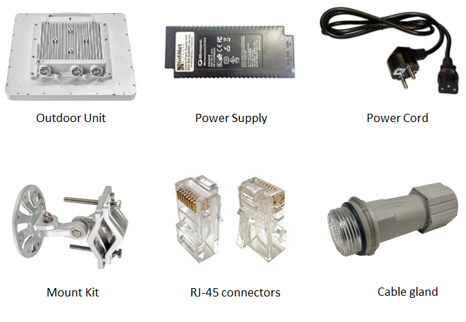
Outdoor Unit
Device with integrated antenna
The outdoor unit can be supplied with an integrated antenna installed in the factory:
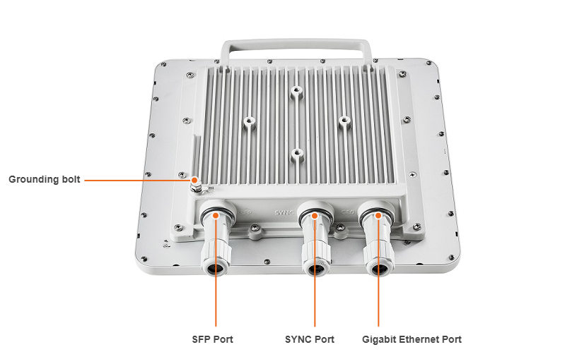
BSI, BSQ
Device based on H16 platform with Gigabit Etheret, SFP and SYNC ports, has LED indicators built-in to the connector housing.
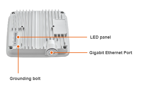
ST (except for the devices with E index)
Device based on H22 platform, available in two options:
- With integrated antenna, except for antennas with 18 dB gain. The device has Gigabit Ethernet port and a LED panel.
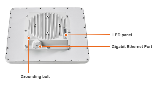
- With integrated antenna 18 dB gain. The device has Gigabit Ethernet port and a LED panel.
Device with connectors for external antenna
The external unit can be supplied in a version with connectors for an external antenna. In this case, a protective cover will be installed instead of the antenna.
BSE
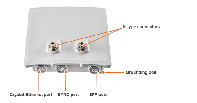
Device based on H16 platform with Gigabit Etheret, SFP and SYNC ports, has LED indicators built-in to the connector housing and two N-type connectors for connecting a dual-polarized external antenna.
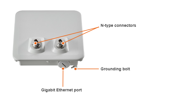
STE
Device based on H22 platform with Gigabit Ethernet port, a LED panel and two N-type connectors for connecting a dual-polarized external antenna.
LED indication
BS
The H16 platform based devices have LED indicators of power and wired connection statuses, built-in to the connector housing. These indicators help to monitor the device's status during the installation. The correspondence between the state of the indicators and the current device state is shown in the table below.
| LED | State | Status | Description |
|---|---|---|---|
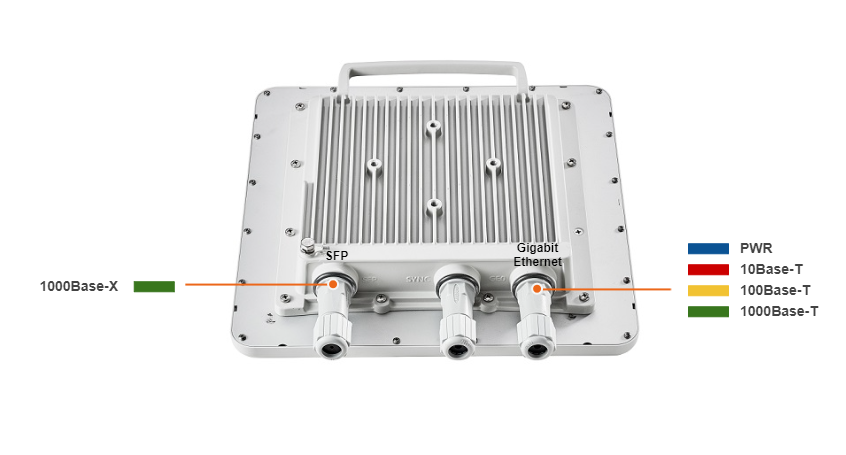
Gigabit Ethernet SFP | Flash | Initialization | The LEDs on both ports light up with white on second. Then LEDs check is performed: red, blue, green are lightened up sequentially. |
Gigabit Ethernet SFP | Flash | Loading | Only for Gigabit Ethernet port: at the beginning green is lightened a few seconds, on the second loading stage switches to blue. |
| Gigabit Ethernet | ON/Blue | Power | Only for Gigabit Ethernet port. |
| Gigabit Ethernet | ON/Red | Speed 10 Mbps | Only for Gigabit Ethernet port. |
| Gigabit Ethernet | ON/Yellow | Speed 100 Mbps | Only for Gigabit Ethernet port. |
Gigabit Ethernet SFP | ON/Green | Speed 1000 Mbps | |
Gigabit Ethernet SFP | ON/Green | ERConsole stage | Port with the established link lights up with green, the second port remains blue. |
ST
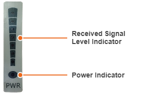
The H22 platform based devices have a special LED indicator panel located at the back of each device, displaying the current device state. PWR - power indicators will light red when the device is connected to a power source, yellow when 10/100 Mbps wired connection appears and green when 1000 Mbps wired connection appears. Other indicators are used to perform coarse antenna alignment. The more indicators are on, the better wireless connection is established. The blinking indicator means an intermediate state. The more often the indicator blinks the higher level connection is established.
Mounting kit
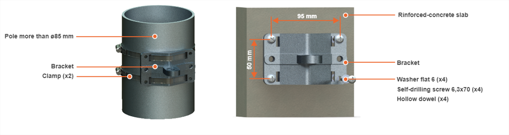
Mounting is carried out on a pole with a diameter 30-85 mm. There are also possible options for mounting on a wall or pole with a diameter more than 85 mm, clamps and other optional fasteners are not included.
MONT-KIT-85
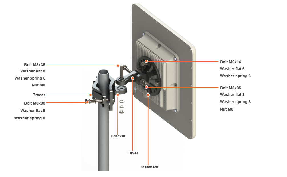
MONT-KIT-85 is supplied by default for all InfiLINK Evolution, InfiMAN Evolution families devices except for devices with an integrated antenna 18 dB gain. MONT-KIT-85 allows to make reliable and easy installation of the unit with two-axis adjustment.
MONT-KIT-85 assembly procedure:
- Attach the basement to the back of the device, using four bolts M6x14, flat and spring washers 6. For easy alignment, set the basement with the prongs to the left.
- Tighten the bracket and the bracer to the pole, using bolts M8x80, flat and spring washers 8. For easy alignment, set the bracket with the prongs up.
- Attach the lever between the bracket and the basement, using bolts M8x35, flat and spring washers, nut M8. Do not fasten the nuts!
- Adjust the required tilt and fasten all nuts at the required position.
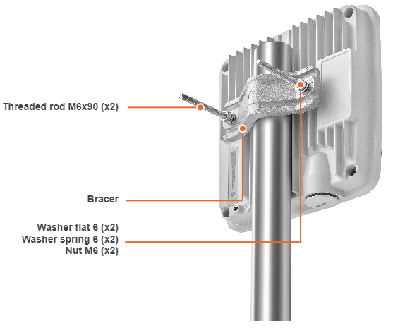
Mounting kit for 18 dBi antennas
E5-ST18 and E6-ST18 models installation is performed using bracer and threaded rod M6x90 that is supplied by default. Install the device according to the scheme below. The nut must be tightened until the spring washer clicks, without over-tightening.
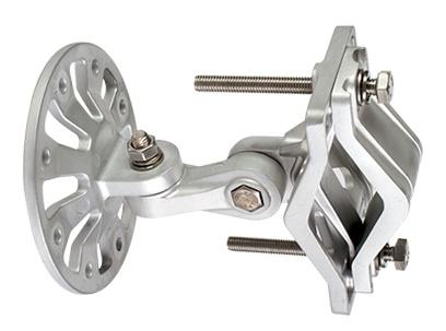
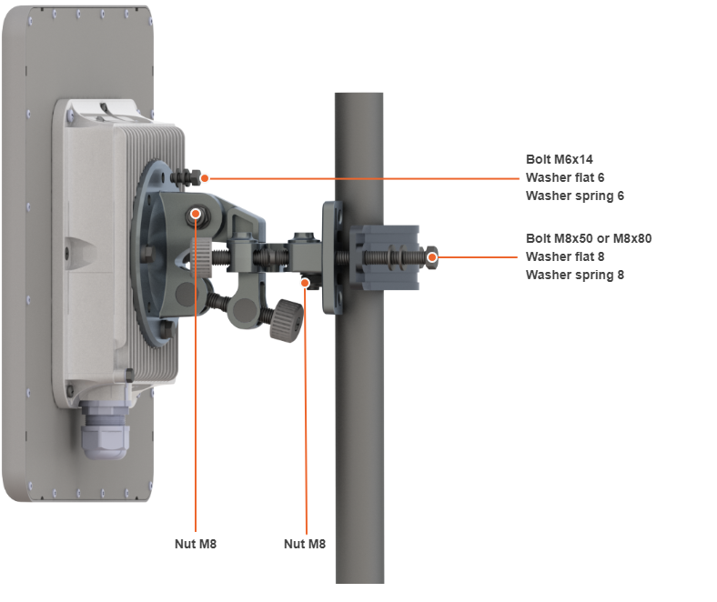
MONT-KIT-85P
For high-precision alignment of devices, especially high antenna gain models, the MONT-KIT-85P can be used (ordered separately).

MONT-KIT-85P assembly procedure:
- Insert and tighten the Assembled kit on the back side of the device using bolts M6x14, washers flat 6 and washers spring 6.
- Tighten the Assembled kit and Bracer to the pole using bolt M8, washer flat 8 and washer spring 8.
- Bolt M8x50 - used for installation on a pole with Ø 30 ... Ø 55 mm.
- Bolt M8x80 - used for installation on a pole with Ø 55 ... Ø 85 mm.
- Perform required antenna alignment using adjustment knobs and then tighten nuts M8.
Note:
M8 nuts are pre-tightened at the manufacturing facility in a position that allows the device to be adjusted using the adjustment knobs and ensures that the wireless device does not shift during the final nuts tighten.
If further adjustment is required, weaken the nuts M8 on about 15 degrees. Do not adjust the knobs without weaken the nuts first.
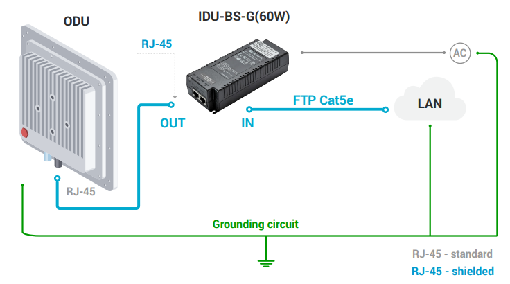
Power supply
A power supply is used to power the device using PoE technology. The default power supply should be connected to AC power source and must be installed indoors.
By default, the following power supplies are included to the package:
| Model | Power supply | Image |
|---|---|---|
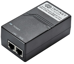
| ST | IDU-CPE-G (24W) |
 |
| BS | IDU-BS-G (60W) | 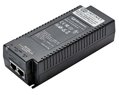 |
Detailed information about the DC power supplies and supplies that can be installed outdoors, are available in the "Grounding and Lightning protection" course.
The package includes:
- Shielded RJ-45 connector for connection to the power supply - 1 pc.
- Standard RJ-45 connector for connection to the outdoor unit - 1 pc or more, depending on the Ethernet ports number of the outdoor unit.
- Cable gland - 1 pc or more, depending on the ports number of the outdoor unit.
Connect the power supply to the outdoor unit according to the scheme below:
Power cord
The model depends on the region, according to the Purchase Order.
Note:
For the connectorized ODU models, you will need external antennas and low loss RF cables, which must be ordered separately.
The Ethernet cables are not included in the package.