InfiLINK Evolution and InfiMAN Evolution - initial link configuration and installation
PtP/PtMP link pre-configuration in the lab
account course progress
Usually, before going into the field, it is recommended to pre-configure in the lab the Infinet Wireless units in order to verify the link establishment. Therefore, let's take the units to be used for this course out of the package and place them on the table.
Test stand assembly
The equipment list required for the lab configuration:
- Outdoor units - 2 pcs.
- Power supply - 2 pcs.
- Power cord - 2 pcs.
- Ethernet cables - 4 pcs.
- Laptop with Ethernet port available.
We will perform the settings mentioned below for each unit and check if the wireless link was established correctly.
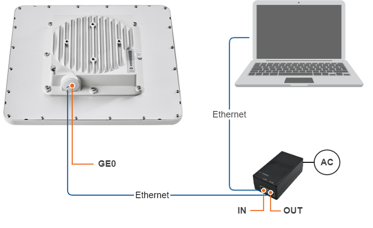
Use the following instruction to assemble a test scheme:
- Connect Gigabit Ethernet port at the ODU to the power supply port labeled as "OUT".
- Connect Ethernet port at the laptop to the power supply port labeled as "IN".
- Connect the power cord to power supply and plug it to AC mains.
Note:
A minimum set of requirements must be met during the device pre-configuration in the lab:
- Make sure that the devices are positioned in such a way so that they are not directed right at each other in order to prevent the device damage
- In case of using a connectorized model (BSE, STE), it is recommended to connect the two devices in the link directly, with RF cables and RF attenuators with attenuation of at least 40 dB for each polarization (installation\deinstallation of the RF attenuators and RF cables should only be performed when the devices are switched off)
- In case of using an external antenna (BSE, STE) or if the other unit in the link is connected to only one N-type connector, do not switch on the unit
Settings via the web interface
We shall perform the settings mentioned below for each unit of the link:
Access to the device
Let's access each unit to the default IP address 10.10.10.1 with mask 255.255.255.0 via a web browser. Before, make sure the Ethernet port of the Laptop has an IP address assigned from the same subnetwork as the one for the unit (e.g., set 10.10.10.10 with mask 255.255.255.0).
Note:
We assume that each unit used in this setup has not been configured before and runs with the factory settings.
Use any letters or numbers for the initial authentication on each unit, for example:
- Login: login.
- Password: password.
Note:
We strongly recommend to change your login and password after the first login.
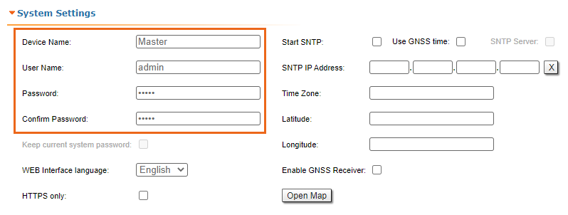
After the first login, let's configure a distinctive name for each unit and set a custom login and password. Go to the Basic Settings section, then to System Settings and configure:
- Device Name (e.g., Master/Slave).
- User Name (e.g., admin).
- Password (e.g., admin).
Note:
At the next login, type "admin" for the User Name and Password (if these are the credentials set before) to access the unit in the privileged mode.
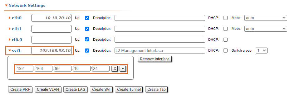
Management IP-address
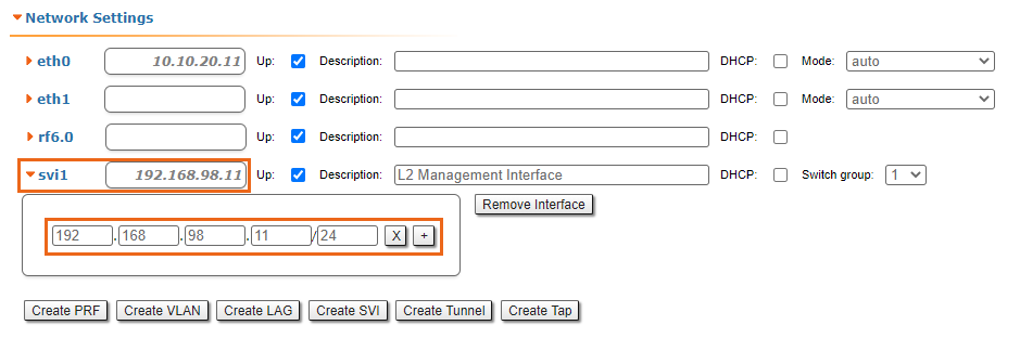
Let's change the management IP of each unit. Go to the "Basic Settings" section, then to Network Settings and change the default IP address of the ‘svi’ interface which is a logical interface used for remote management access in MINT switching mode (MINT switching mode is enabled by default).
Network settings for Master:
Network settings for Slave:
Firmware upgrade
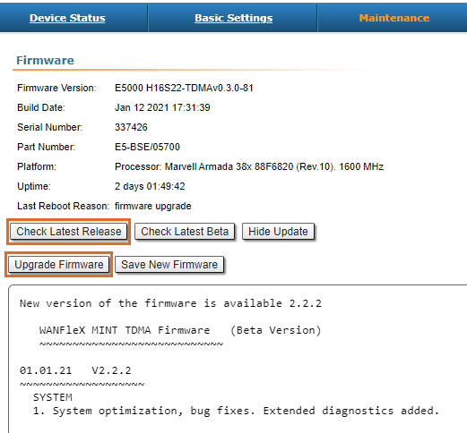
Let's upgrade each unit to the latest stable firmware version. Go to the Maintenance section and click on the "Check Latest Release" button. In case a new software version is available, click on the "Upgrade Firmware" to initiate the firmware upgrade process. Before, make sure the laptop which is connected to the unit has an Internet connection, too. Otherwise, the manual firmware upgrade process should be performed.
Radio parameters configuration
Let's configure the minimum needed radio parameters to establish the link.
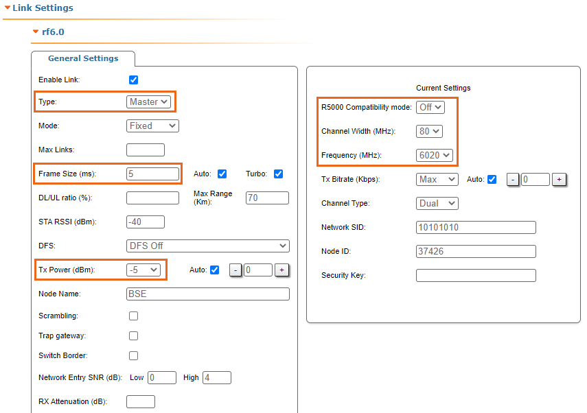
At the unit named Master at step above, go to the "Basic Settings" section, then to "Link Settings" and set this unit with:
- Type: Master.
- Tx Power: e.g., -5 dBm (set the minimum value in the range, as currently, we are in the lab, and we don't need high output power anymore).
- Node Name: e.g., Master (it is the same as the value set at Device Name if this was saved before).
- R5000 Compatibility mode: off (if compatibility with InfiLINK 2x2 / InfiMAN 2x2 families devices is not required).
- Channel Width: e.g., 80 MHz.
- Frequency: e.g., 6020 MHz.
- Frame size: e.g., 5 ms.
The rest of parameters remain with the default values.
At the unit named Slave at step above, go to the Basic Settings section, then to Link Settings and set this unit with:
- Type: Slave.
- Tx Power: e.g., 0 dBm (set the minimum value in the range, as currently, we are in the lab, and we don't need high output power anymore).
- Node Name: e.g., Slave (it is the same as the value set at Device Name if this was saved before).
- Channel Width: e.g., 80 MHz.
- Frequency: e.g., 6020 MHz.
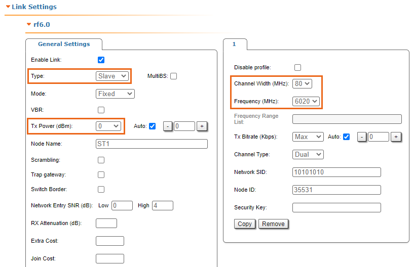
The rest of parameters remain with the default values.
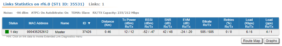
Check the wireless link status
Let's apply all settings described above for each unit and after login let's go to the Device Status section, and check the link establishment at Link Statistics.
Master Link Statistics:

Slave Link Statistics: