InfiLINK Evolution and InfiMAN Evolution - initial link configuration and installation
Link installation and commissioning
account course progress
Before mounting the equipment in an outdoor environment, please make sure that:
- You acknowledge the regulations imposed by the Regulatory Authority for Communications in your country for the radio spectrum to be used.
- You chose known locations for the installation of the links; although Infinet Wireless devices can also operate in Near-LoS or Non-LoS conditions, to achieve the best performance, it's highly recommended to install the link in locations where Clear-Line-of-Site and clear channels are available.
- You performed link planning using the InfiPLANNER tool (https://infiplanner.infinetwireless.com) to determine the link path profiles, radio equipment placement requirements, etc.
- You met requirements described in the "Planning considerations" lesson.
Installation Procedure
In case of device with external antenna. Prepare RF cables of the required length, recommended maximal length is 1 meter. Install and isolate the connectors on the RF cable. In order to prevent device damage make sure that antenna is connected to both N-type connectors with serviceable RF cables before switching on.
- Install ODU connector facing down using the mounting kit. Do not tighten the fasteners to the end until the alignment is completed.
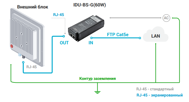
- Connect the Cat5e FTP cable with the cable gland to ODU.
- Perform ODU grounding.
- Lay the Cat5e FTP cable from ODU to the power supply.
Connect the Cat5e FTP cable with a shielded connector covered by a cap to the "OUT" port of the power supply, having previously touched the power supply connector case with FTP cable connector case. The power supply must not operate near a direct heat source, near water or in an environment with high humidity. The cables must be connected in such a way to prevent water flow to the power supply connectors.
- Perform the power supply grounding.
- Connect the laptop using Cat5e FTP cable to the power supply "IN" port.
Connect the power cord to the power supply and then to the power circuit.
- Make sure a small loop (at least 10 cable diameters) is provided before the Cat5e FTP cable enter into the building.
Note:
Missing or improper grounding can damage the device in case of a lightning strike.
We recommend you to study the "Grounding and Lightning protection" course before installing the device.
Note:
Please note that the pressure equalization system in Infinet devices is performed via gas exchange through a cable gland and Ethernet cable jacket with a dry room where the power supply is installed. In order to avoid ODU failure due to moisture entering the device, for example, during the pressure drop during the rain, the cable gland assembly requirements should be met and there are should be no cracks in the Ethernet cable jacket.
In addition, you should avoid the Ethernet cable bending near the ODU, that can bring to the pressure equalization system fault between the internal volume of the sealed ODU and the external environment during a sudden air temperature change. This may lead to the device failures.
Antenna alignment
Rough alignment
Using the azimuth and elevation values computed by the link planning tool roughly position the antenna (in each location) to detect the opposite system signal. Directly before installing the devices we recommend to set up the maximum output power value. If the link cannot be established, try to switch the bitrate to the minimum value and narrowing the channel width. If link is not established after this actions, please proceed to the "Troubleshooting" article of the technical documentation.
Assess the link establishment and its quality using the LED indicator on the device case. LED indication are detaily described in the "What’s in the box?" lesson. For more accurate alignment, use the alignment tool built into the device web interface.
Precise alignment
It is recommended to have two teams prepared for alignment procedure, each team with at least two installers: one should notisy the signal values and communicate with the remote side, the other should make the adjustments with the device. After the initial approximate alignment (link up), the antenna with the lowest gain should be locked into position.
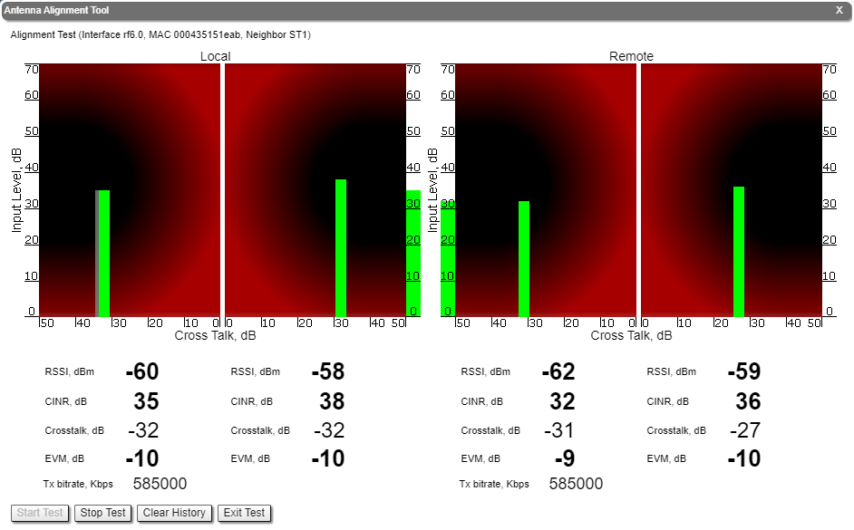
Both teams should use the Antenna Alignment Tool in the Device Status section of the web GUI. In order to start the alignment, in the "Link statistics for the rf6.0 interface" section, left-click on the link need to be aligned, select the "Antenna alignment" option.
The team at the antenna which has the highest gain will start to change the azimuth slowly while watching the signal indicators
- As soon as the best signal has been found (Input Signal stripes must be located in the black area, closer to its center), the antenna must be locked into that position
- The same action will be performed for the elevation, and the antenna must be locked into the final position where both elevation and azimuth provide the best signal, according to the indicators provided by the antenna alignment tool:
- EVM: higher than 21 in absolute value.
- Signal level to interference and noise: higher than 28 dB.
- Retries: lower than 5 %.
Note:
No contact should be made with the antennas during signal reading because the human body can affect the radiation pattern of the antenna and signal readings.
The main parameters displayed in the alignment tool:
- RSSI - indicates the power level of the received radio signal, optimal parameter value -60 ... -40 dBm.
- CINR - input signal level to noise + interference indicator, >=28 dB.
- Crosstalk - indicates how much vertically and horizontally polarized signals influence each other, >20 dB in absolute value.
- Error Vector Magnitude (EVM) - indicator of the measured input signal quality (it should be as high as possible in absolute value, the recommended level is not less than 21 dB in absolute value. Some old firmware had EVM value positive, but most the firmware has negative value, so for the troubleshooting, evaluate the absolute EVM value).
- Tx bitrate - displays the current bitrate for the remote and local units (measured in Kbps).