Wireless Networking Fundamentals
Radio waves main characteristics
account course progress
Radio waves are electromagnetic waves propagated in a medium. In wireless communication systems, a medium is a free space where the speed of wave propagation corresponds to the lightspeed. The source of the electromagnetic wave is a conductor - an antenna through which an alternating-current flows. Please note, that the electromagnetic field will only exist around the conductor through which the alternating-current flows, and the energy radiated by the conductor and the strength characteristics of the field will correspond to the AC flowing.
Radio waves nature
It is known that an electric field is formed around an electrified body, and a magnetic field - around a conductor with alternating-current. Let's look at an unclosed conductor - a vibrator, which charges are distributed unevenly, as it is shown in Figure 1:
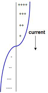
Figure 1 Distribution of charges along the vibrator body
Since the charge is distributed unevenly along the vibrator, an electric field forms between the separate sections of the conductor, because of which the motion of charges will start and electrical oscillations appear. The alternating electric field around the vibrator creates an alternating magnetic field, which in its turn forms an alternating electric field. This ensures the propagation of an electromagnetic radiation in the space and is called the electromagnetic wave.
Polarization
Polarization is the characteristic of electromagnetic waves, which is defined as orientation of the electric field intensity vector, which is perpendicular to the direction of the wave propagation and the magnetic field vector.
There are three types of polarization: linear vertical, linear horizontal and circular, as it is shown in Figure 2. There are also particular types of polarizations: angular (vector of the electric field intensity is directed at an angle of 45 degrees) and elliptic (end of the electric field vector makes an ellipse in plane of oscillations).
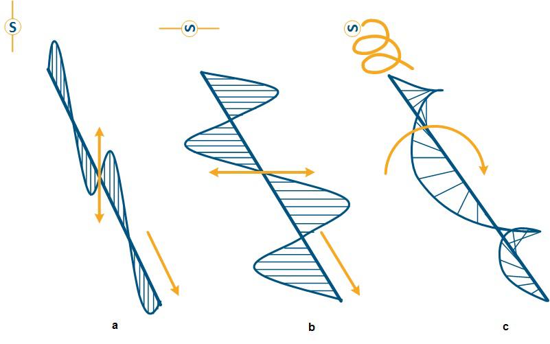
Figure 2 Electromagnetic waves polarization: a - linear vertical, b - linear horizontal, c - circular
A polarization type depends on the radiation source. It is necessary to make receiver coordinated by the polarization with the transmitter to establish effective connection.
Because of the fact the electric current induced by the horizontal polarization wave in the vertically mounted vibrator will be minimal due to misalignment of the receiving and transmitting sides, waves of horizontal and vertical polarization will not affect each other. A similar effect will appear in the interaction of two angular polarized waves with 90 degree different angle of rotation. Low interference between two radio signals with different polarization can be used to increase the capacity of the communication system: due to simultaneous transmission of a signal with vertical and horizontal polarizations in one frequency band, the throughput is doubled.
Wave basic characteristics
Since the electromagnetic wave is formed in accordance with the alternating current in the vibrator, the distribution of the electric and magnetic field intensity will be periodic in nature. Like any oscillation, it can be described by the following concepts:
- amplitude;
- wavelength;
- frequency;
- phase.
In order to describe basic characteristic of electromagnetic oscillation, let's look at Figure 3, which shows the distribution of electric field intensity in time:
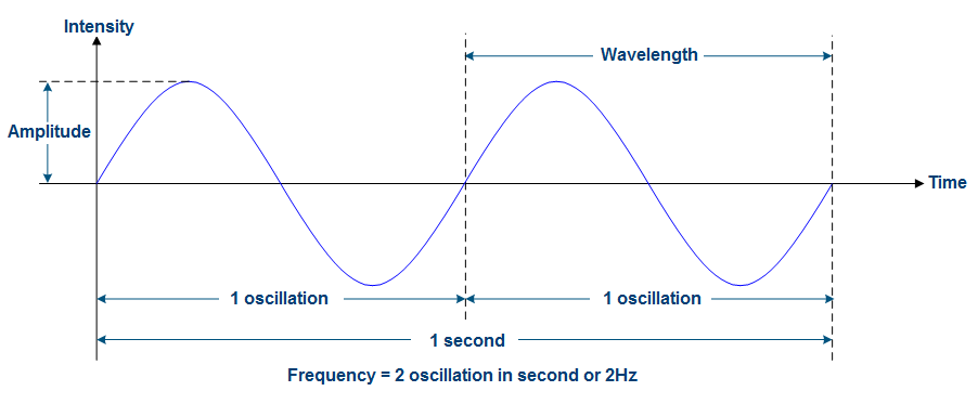
Figure 3 The distribution of field intensity in time
Amplitude - the maximum value of displacement of the field intensity from its average value. Unit of measurement - Volt/meter (V/m).
Frequency - the number of periodic processes repetitions per unit time. Unit of measurement - Herz (Hz). In Figure 3 there are two complete oscillation in one second, so the frequency is:
Wavelength - the distance to which the wave moves during one oscillation. Unit of measurement - meter (m). This parameter is related to the frequency by the speed of propagation of the electromagnetic wave, which in free space corresponds to the lightspeed:
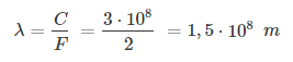
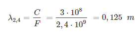
So wavelengths are:
for 2,4 GHz
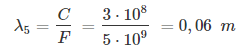
and for 5 GHz:
In the general case, the expression describing the oscillatory process looks as following:

In this formula, the sinus function argument is called the complete phase and describes the wave process in time. The initial phase, which is part of the complete phase, determines the initial state of the oscillatory process.
Radiofrequency spectrum
A common tools for analyzing signals are oscillograms - relations of voltage and current from time. Oscillograms help to track the form of signal and its character variation in time. However, while forming complex signals or analyzing real communication systems, a convenient tool for spectrum analysis is the frequency spectrum. The frequency spectrum is a dependence of intensity of electromagnetic radiation on frequency. It allows to estimate utilization of the frequency range by communication systems and other sources of electromagnetic waves. Both tools of oscillograms and spectral characteristics are not interchangeable and are used simultaneously.
There is definitive relation between time and frequency characteristics: according to the Fourier theory, the signal oscillogram can be represented as a sum of harmonic oscillations of multiple frequencies which are called harmonics. Thus, a periodic frequency signal F can be represented as a sum of sinusoids with frequencies F, 2F, 3F, etc., it allows to estimate each harmonic separately and to form the spectral characteristics. The consequence of this transformation is that the signal spectrum becomes infinite due to higher harmonics. In practice, the signal spectrum is limited by filters, higher harmonics are removed due to making a small contribution to the total signal because of the small amplitude.
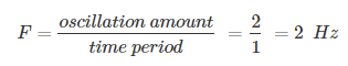
Figure 4 displays the spectrum of the harmonic signal shown above:
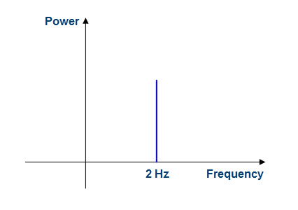
Figure 4 Frequency spectrum of a harmonic signal, where F=2 Hz
Such signal is not a carrier of information because it is possible to predict its behavior at any time by estimating the signal parameters on the receiving side. For transmission of information one or more of the considered signal characteristics - amplitude, frequency or phase, might to be changed in accordance with the information message, in this case the original harmonic signal is called the carrier. These processes will be described in details in the section 6. Analog and digital signals
Let's demonstrate the advantage of using the frequency spectrum in compare with time diagrams. In addition to existing signal, form 3 Hz frequency signal:
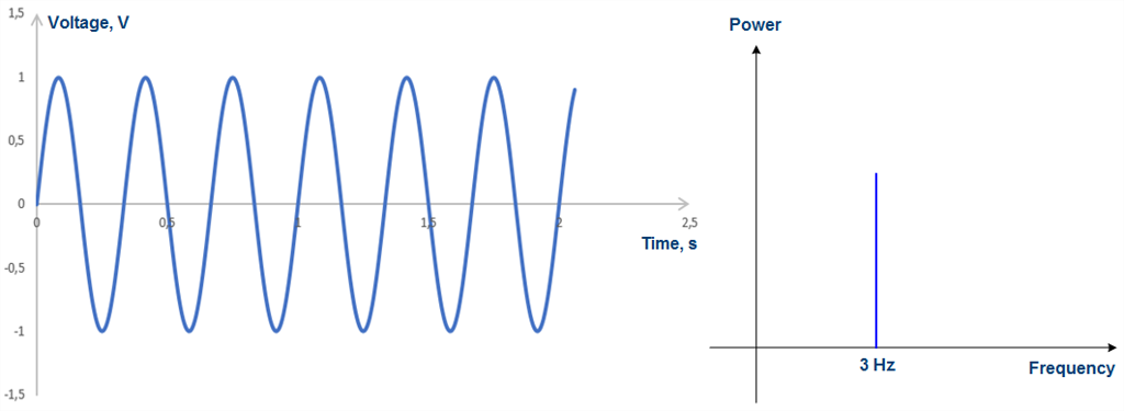
Figure 5 Voltage oscillogram and frequency spectrum of a harmonic signal, where F=3 Hz
Summarize the received signals and estimate the spectrum of the joint signal. As it is shown in Figure 6, it is difficult to get information about the harmonic components from the oscillogram, however, the spectral characteristic allows to do that unmistakably:
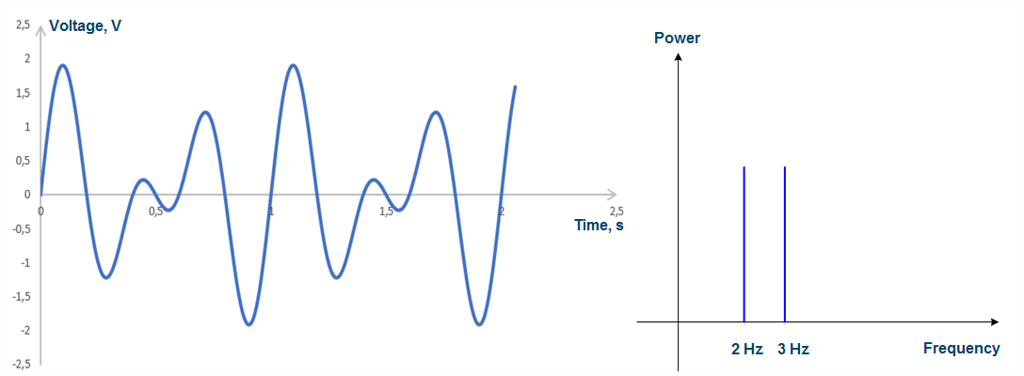
Figure 6 Voltage oscillogram and frequency spectrum of a joint signal
The consequence of modulation of the carrier signal is the expand of the spectrum, so the communication system uses for the transmission of informationand not only a carrier but a frequency band.
Figure 7 demonstrates frequency spectrum which shows the operation of three communication channels:
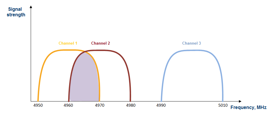
Figure 7 Frequency spectrum with simultaneous operation of three communication channels
Described communication systems are configured to the following frequencies:
| Num | Central frequency, MHz | Band, MHz |
|---|---|---|
| Channel 1 | 4960 | 20 |
| Channel2 | 4970 | 20 |
| Channel3 | 5000 | 20 |
Frequency spectrum shown in Figure 7 demonstrates frequency crossing at communication channels 1 and 2, this will lead to negative consequences in the form of mutual influence. Channel 3 doesn't have frequency crossing with different communication systems, also due to guarding interval between channels 2 and 3, an influence of these communication systems on the channel 3 will be minimal.
Frequency band
According to the regulations developed by the International Telecommunication Union (ITU), the following frequency bands are distinguished:
| Band number | Designation ITU | Band name | Frequency band | Application |
|---|---|---|---|---|
| -1 | ELF | Gigametric waves | 0,03-0,3 Hz | |
| 0 | ELF | Hectomegametric waves | 0,3-3 Hz | |
| 1 | ELF | Decamegametric waves | 3-30 Hz | Communication with submarines, geophysical research |
| 2 | ELF | Megametric wave | 30-300 Hz | Communication with submarines, geophysical research |
| 3 | ULF | Hectokilometric waves | 300-3000 Hz | Communication with submarines |
| 4 | VLF | Myriametric waves | 3-30 kHz | Exact time service, communication with submarines |
| 5 | LF | Kilometric waves | 30-300 kHz | Radio broadcasting, ground-based radio communication, navigation |
| 6 | MF | Hectometric waves | 300-3000 kHz | Radio broadcasting, ground-based and ionospheric radio communication |
| 7 | HF | Decametric waves | 3-30 MHz | Radio broadcasting, ionospheric radio communication, over-the-horizon radar, radio stations |
| 8 | VHF | Metric waves | 30-300 MHz | Television, radio broadcasting, tropospheric and direct-wave radio communication, radio stations |
| 9 | UHF | Decimetric waves | 300-3000 MHz | Television, radio broadcasting, tropospheric and direct-wave radio communication, mobile phones,radio stations, ultrahigh frequency treatment, microwaves ovens, satellite navigation |
| 10 | SHF | Centimetric waves | 3-30 GHz | Radar, Internet, satellite television, satellite and radio direct-wave communication, wireless computer networks |
| 11 | EHF | Millimetric waves | 30-300 GHz | Radio astronomy, high-speed radio relay communication, radiolocation (meteorological, weapon control), medicine, satellite radio communication |
| 12 | Decimillimetric waves | 300-3000 GHz | An experimental "terahertz camera" recording an image in a long-wave IR | |
| 13 | Centimillimetric waves | 3-30 THz | ||
| 14 | Micrometric waves | 30-300 THz | ||
| 15 | Decimicrometric waves | 300-3000 THz |
Regulatory work
Using of a frequency resource is governed by state policy, so an important aspect in the operation of wireless communication systems is the authorization from the state authorities and using certified equipment. Since equipment operating on adjacent frequencies can have influence on each other, an important indicator of certification is the frequency mask that determines the level of out-of-band radiation. For example, the frequency mask of the 20 MHz signal for wireless equipment operating in the frequency range 5150-6425 MHz, is following:
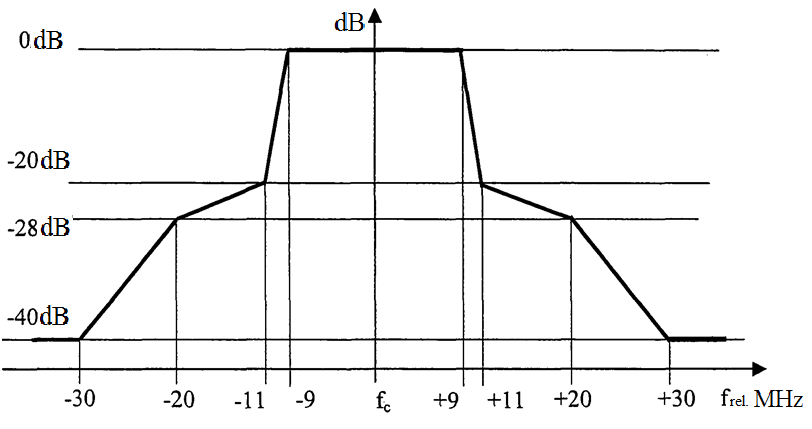
Figure 8 The frequency mask for wireless equipment operating in the frequency range 5150-6425 MHz with 20 MHz band
Thus, it is permitted to use an equipment with out-of-band radiation 20 dB lower than the band signal power. It should also be noted that a radiation requirements become stricter with increasing distance from the center frequency of channel: so for a frequency remoted at 30 MHz from the center, the requirements for out-of-band radiation are -40 dB.
For the signal with 40MHz band:
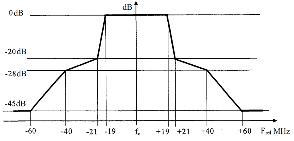
Figure 9 The frequency mask for wireless equipment operating in the frequency range 5150-6425 MHz with 40 MHz band