MINT Switching
MINT protocol
account course progress
The switching and routing definition
Switching is the data link level technology (L2), designed to connect network subscribers through transit nodes. The switching provides nodes connectivity within one network, connectivity between networks is provided by network layer technologies. Thus, by the data link technologies, local devices are combined, and with the help of network - remote ones.
In computer networks, data units switching is based on their MAC address and Ethernet protocol, as the dominant technology. A unit of data used in switching is called a frame.
A device that commits switching is called a switch. Switch ports and forwarding traffic possible paths between ports form a switching matrix.
Routing is a network layer technology (L3) designed to connect networks. IP is the dominant network layer technology in the computer networks. A unit of data used in routing is called a packet.
Note that switching and routing technologies do not compete, but complement each other. So, in the general case, data transmission within a communication channel is based on L2 headers, and data transfer between networks is based on third level headers.
The difference in the data units processing is that L2-headers can be processed by hardware switching matrices, and L3 - by the device CPU. Switching matrices have a significant advantage relative to CPU in data processing speed, however, the network (L3) level allows to use complex network protocols and provides data transmission flexibility.
Basic MINT protocol principles
MINT (Mesh Interconnection Network Technology) - proprietary Infinet technology, used in InfiLINK 2x2, InfiMAN 2x2, InfiLINK Evolution and InfiMAN Evolution families devices, providing data transfer between devices via wireless and wired links.
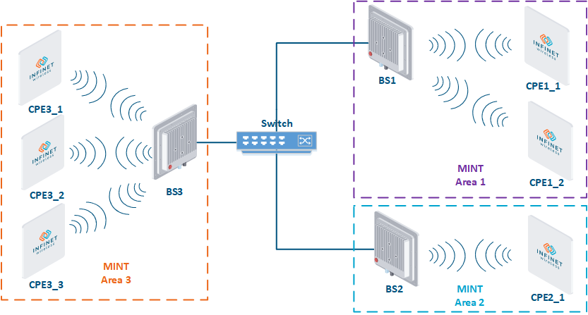
Boundaries of the MINT technology application is the MINT area. A MINT area is a set of devices connected through a common radio environment. It is also possible to combine several MINT areas into one through wired links, it will be shown in the following lessons. In the figure above, the BS1, CPE1_1 and CPE1_2 devices are in the same MINT area, and the BS2 and CPE2_1 devices are in the other, using of MINT technology functionality between the BS1 and BS2 devices is impossible, since they are located in different MINT areas.
The MINT architecture supports two basic ways of traffic transmittion — switching and routing. Each frame that will be transmitted through the MINT area is first checked for matching with the switching rules. If the frame matches to the rules, it will be transmitted within the MINT area; if not, the frame is passed to the routing module, which makes the final decision about its redirection.
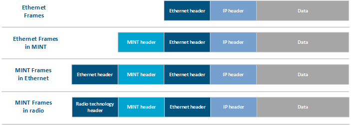
The advantage of MINT is its transparency for high-level protocols. For example, an Ethernet frame with a VLAN tag can be transmitted through the MINT area without changes, same way as via cable. The structure of the Ethernet frame encapsulated in MINT is shown in the figure above. Thus, the MINT area becomes a virtual switch for external devices. In addition, when encapsulating an Ethernet frame into a MINT frame, the Packet Header Supression mechanism is applied, compressing the redundant part of the frame, and combining small frames into Burst superframes.
A header is also added to MINT frames during transmission through a radio link, is depending on the radio technology used. Polling and TDMA technologies can be used on the InfiLINK 2x2 and InfiMAN 2x2 families devices. InfiLINK Evolution and InfiMAN Evolution families devices can only operate with TDMA technologiy software.
Also it is possible to encapsulate MINT frames into Ethernet frames through a pseudo-radio interface, which is detaily discussed in the following lessons. The structure of such frame is shown in the figure above. This tool allows to combine MINT segments into a single area using wired or wireless L2 channels built using network equipment from other manufacturers.
To create MINT connections, communication between adjacent nodes is required. Forming the broadcasting ARP requests, the InfiNet devices compile a MAC addresses list of devices connected to the MINT. Thus, each node of the MINT network has a complete MINT network map containing information about neighbors and routes.
The MINT routing table contains all possible routes to all destinations of the MINT network and, like OSPF, the least cost route is selected during data transmission, however, the switching table is built and searched using the MAC address. Each node recalculates the link cost value with its neighbors every 1-3 seconds. The device, when calculating the cost, operates with values of the parameters SNR, RSSI, bitrate, repeat rate, channel loading, etc., therefore the routes between the MINT areas can change unpredictably depending on the link quality.