MINT Switching
Traffic redundancy schemes
account course progress
Common link redundancy scheme. Application area
The Infinet equipment supports various traffic reservation schemes in the "1+1" mode. Hot standby can be built according to a scheme in which the main and backup links are organized with the InfiNet devices by using transmitting and receiving elements duplication.
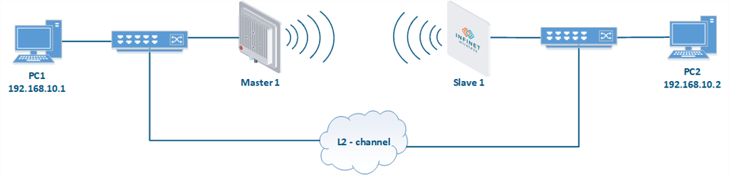
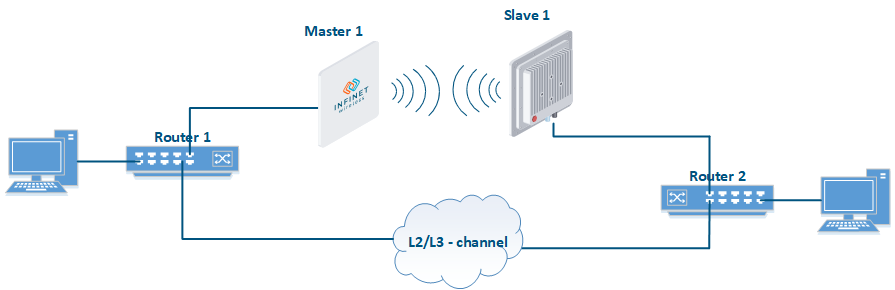
Generally, the redundancy scheme consists of two communication channels: an arbitrary L2 link and a radio link on the InfiNet equipment (see figure above). The link selection for direct traffic transmission is based on the one of service protocols running on the Infinet devices or on the other manufacturers network equipment. Such protocols are:
- MINT "Failover";
- switching loop prevention protocols (STP for example);
- dynamic routing protocols (OSPF for example).
MINT "Failover" application
Infinet devices of InfiLINK 2x2, InfiMAN 2x2, InfiLINK Evolution and InfiMAN Evolution families allows to build a redundant links. MINT "Failover" option allows to configure hot standby for any link, wired or wireless. In this case, the main link equipment type is not important. The only condition is connectivity at the L2 level between InfiNet devices through both communication links.
The operation principle is very simple. The Infinet device, on which the MINT "Failover" is activated, checks for the specific MAC address presence in frames transmitted through the main link. If these frames with specified MAC address are present, then the backup link operation is blocked. In this case the master device of the backup radio link turnes off the radio module and stops broadcasting, and the slave device only "listens" to the air. If as the main link is also used radio, the backup and main links can operate on the same frequency without mutual influence. When the monitored MAC address disappears from frames headers received by the device through the primary link, the backup link starts to transmit the traffic. The process is fully automatic. However, the transition to a backup link cause a short connectivity interruption. The traffic transmission through the main link will be resumed only after the failure of the backup link.
If devices of InfiLINK 2x2, InfiMAN 2x2, InfiLINK Evolution or InfiMAN Evolution are used for main link, the link selection parameters can be set manually.
It is also possible to connect two Infinet devices to one external antenna or use one radio frequency.
MINT "Failover" over the L2-link
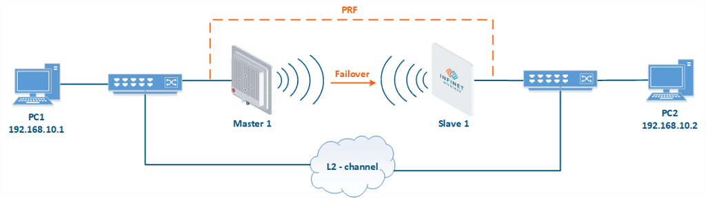
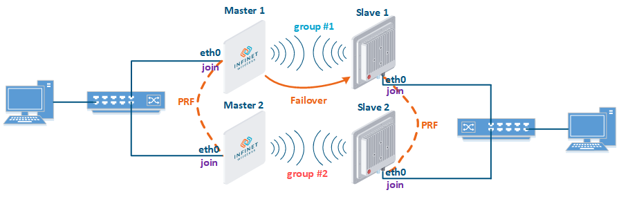
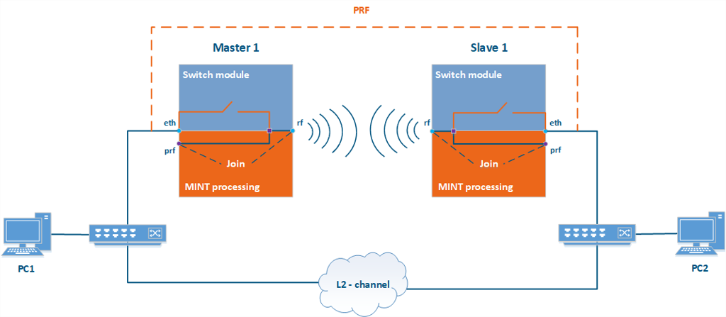
In case the radio link between the Infinet devices is used as the backup link, and an arbitrary link is used as the main link, the configuration is performed in two steps:
- PRF interfaces are created on the Master 1 and Slave 1 devices.
- Enable MINT "Failover" option on the Master 1 device with Slave 1 MAC address tracking.
In this case, the Master 1 device will receive frames with the Slave 1 MAC address in two ways: by the RF interface via the backup radiolink and by the PRF interface via the main channel. By default, the PRF interface has less cost than RF, so the radio interface of the Master 1 device will be turned off. If the main link fails, the Master 1 device will stop receiving frames with the monitored Slave 1 MAC address and turn on the radio interface. The connection between PC1 and PC2 will be restored via the backup radiolink. At the time when the main link is restored, the Master 1 device will start to receive frames with the monitored MAC address via two links and turn off the radio module again.
The described redundancy configuration consist of the following steps:
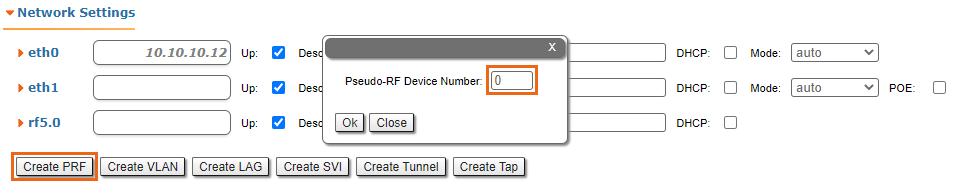
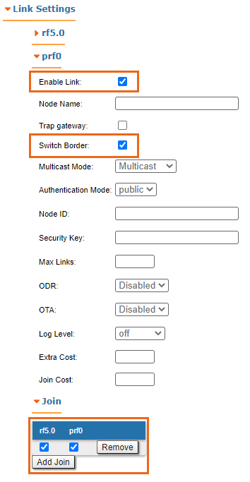
1. PRF interface configuration: go to the "Network Settings" section and click the "Create PRF" button. After that go to the "Link Settings" section, activate created PRF interface, enable the "switch border" option and join it with RF interface:
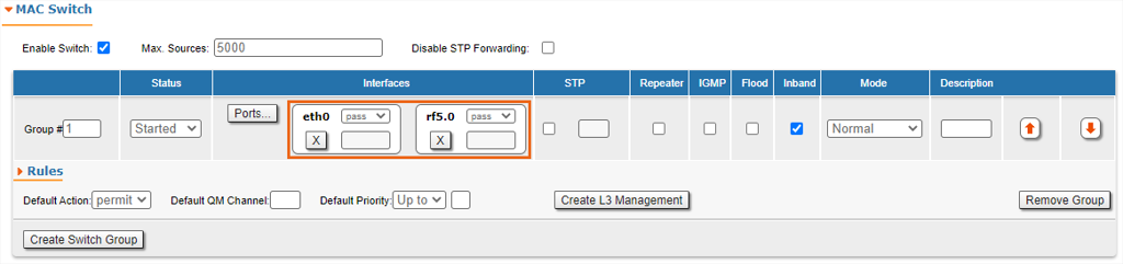
2. Switch groups configuration: It is necessary to create switch groups on Master 1 and Slave 1, and add eth* and rf* interfaces:
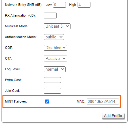
3. MINT "Failover" configuration: go to the "Link Settings" section, enable MINT "Failover" option and enter the Slave 1 MAC address, or left this field empty for automatic MAC address detection:
MINT "Failover" over the radio between Infinet devices
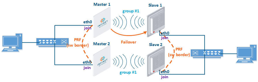
If both links main and backup are built on Infinet devices of the InfiLINK 2x2, InfiMAN 2x2, InfiLINK Evolution or InfiMAN Evolution families, on the radio link selected as a backup, a higher cost must be set manually. To avoid loops on PRF interfaces, one of the following schemes must be used:
- different switch group identifiers should be used on the main and backup links;
- the "switch border" option must be activated on the PRF interfaces of one of the links.
MINT "Failover" with different switch group identifiers:
Device configuration is performed in the following sequence:
- Step 1: create PRF interfaces on all devices;
- Step 2: join the RF and PRF interfaces on all devices;
- Step 3: create switch groups on all devices:
- Step 3a: create switch group #1 at the Master 1 and Slave 1 devices;
- Step 3b: create switch group #2 at the Master 2 and Slave 2 devices;
- Step 4: activate the MINT "Failover" option on the Mater device of main link, in our example it is Master 1 device. The Slave 1 MAC address must be specified as the tracking address for the Master 1, or left this field empty for automatic MAC address detection.
- Step 5: set any high value of the "Extra Cost" parameter on both devices of the backup link, for example, 5000.
MINT "Failover" with using "switch border" option:
Device configuration is performed in the following sequence:
- Step 1: create PRF interfaces on all devices, the "switch border" option must be activated on the PRF interfaces of one of the links;
- Step 2: join the RF and PRF interfaces on all devices;
- Step 3: create switch group #1 on all devices
- Step 4: activate the MINT "Failover" option on the Mater device of main link, in our example it is Master 1 device. The Slave 1 MAC address must be specified as the tracking address for the Master 1, or left this field empty for automatic MAC address detection.
- Step 5: set any high value of the "Extra Cost" parameter on both devices of the backup link, for example, 5000.
Scheme using MINT "Failover" on both links:

Device configuration is performed in the following sequence:
- Complete Steps 1-3 according to one of the above suggested schemes;
- Step 4: activate the MINT "Failover" option on the Mater device of main link, in our example it is Master 1 device. The Slave 1 MAC address must be specified as the tracking address for the Master 1, or left this field empty for automatic MAC address detection.
- Step 5: activate the MINT "Failover" option on the Mater device of main link, in our example it is Master 2 device. The Slave 2 MAC address must be specified as the tracking address for the Master 2, or left this field empty for automatic MAC address detection.
Note:
The link with the best radio characteristics will be selected as the main, however, in case of similar conditions, this can lead to a frequent change of the main channel and interruptions in the network operation. When implementing this scheme, we recommend to set the "Extra Cost" parameter on the link selected as a backup.
STP
In case an arbitrary L2 channel is main, and the backup link is a radio channel between Infinet devices operating in the switching mode, there is a risk of a switching loop. Loops occurrence mechanism is described in the previous lesson. STP (spanning-tree protocol) is one of the solutions for loop prevention and fault tolerance.
STP using on the Infinet units
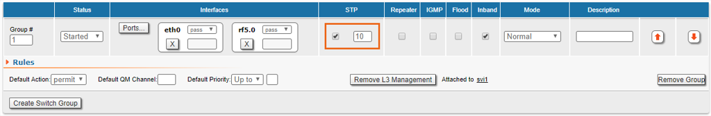
The STP protocol can be started on Infinet devices during switch groups configuration. In this case, the equipment will look for loops and prevent them by disabling the traffic transfer through some switch groups interfaces. An example of the STP operation is shown in the figure below. At the same time, in case of main link failure, the protocol will track this and change the data transfer scheme using a backup radiolink.
Create PRF interfaces and switch groups on Master 1 and Slave 1 devices. In switch group settings activate the STP operation and set the VLAN number associated with this switch group:
In case the main link is a radio link between Infinet devices, apply the configuration above to all wireless devices.
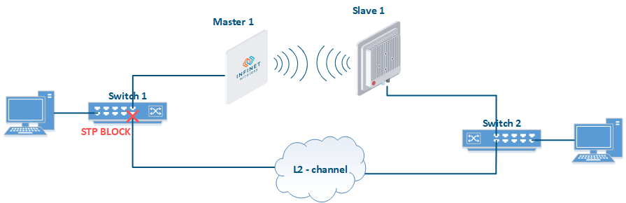
STP on network equipment of other manufacturers
It is possible to implement a hot standby scheme in which the STP is started on the network equipment of other manufacturers, and the Infinet wireless devices are used for the main and / or backup radio link. Such scheme is shown on the figure below. STP is enabled on Switches 1 and 2. By exchanging service BPDU frames, switches build a tree structure and, in the case of loop detection, block one of the ports. On the figure below, STP on switch 1 blocked the port to an arbitrary L2 link, choosing a radio link as the main for data transmission.
To implement this scheme, no additional settings on the Infinet devices are required - it is enough to create switch groups.
OSPF protocol
One more method of building redundancy schemes is using dynamic routing protocols. In this the OSPF protocol will be reviewed, but using of any other routing protocol will not be significantly different.
OSPF protocol using on network equipment of other manufacturers
Infinet devices support the OSPF protocol operation, but this course is to show the switching mode so we assume that the dynamic routing protocol is running on the network equipment of other manufacturers. The redundancy scheme is shown in the figure below.
OSPF is started on routers 1 and 2, which are connected by two links: a backup radio link between the Infinet devices and an arbitrary L2/L3 link as the main. After successfully neighbor relations establishing and LSDB messages exchanging, routers calculate routes to each of the known networks and add them to the routing table. User traffic will be transmitted through the main link, but in case of its failure, the route through the radiolink will become active.
The Infinet devices configuration is the same as in the previous example - it is enough to create switch groups.
Redundancy in scheme with mobile objects
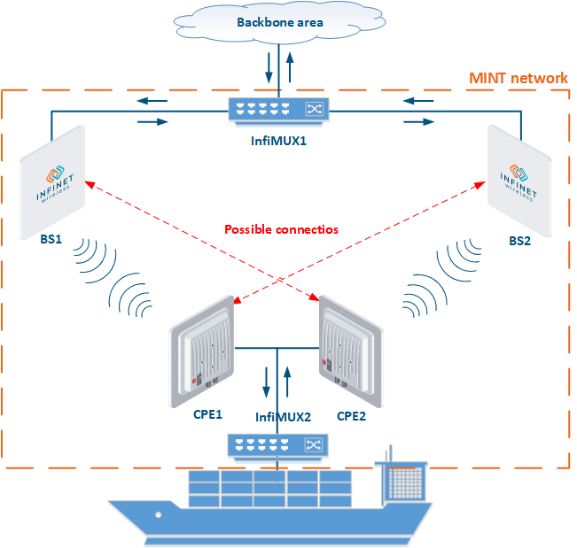
Popular scenario in projects with mobile objects is the situation when base stations are installed along the object's movement path, and two subscriber terminals are mounted on the object. Using of two subscriber stations allows to increase the reliability of communication due to the radiation pattern expansion: subscriber terminals are mounted with different azimuths, therefore, at least one subscriber terminal will be in the coverage area of one Base Station sector.
The example of using two Base Stations sectors is shown in the figure below. A mobile object is a cargo ship plying in a limited water area, constantly located in the coverage area of at least one Base Station sector. The ship has two subscriber terminals which provide fault tolerance for a wireless connection:
- in ship central position (see Figure) CPE1 is connected with BS1, CPE2 - with BS2;
- in the leftmost position CPE2 is connected with BS1;
- in the rightmost position CPE1 is connected with BS2.
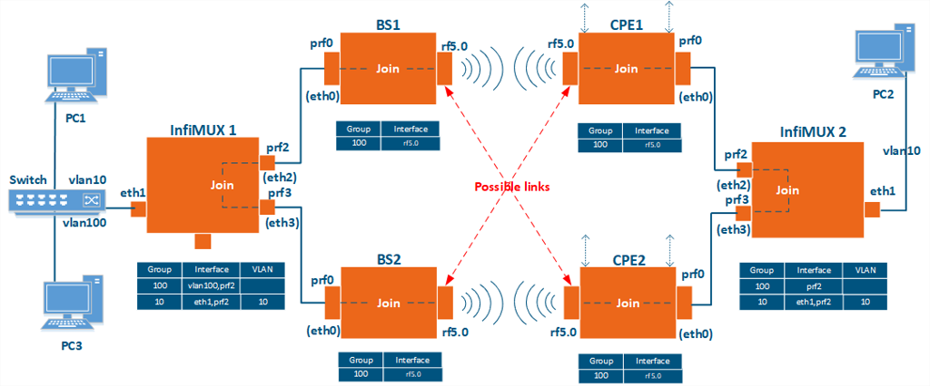
To explain the device configuration, let's look at the scheme in figure above from different point of view. The scheme with configuration units is shown in figure below:
- The ship has the user device - PC2, which is connected to CPE1 and CPE2 via the InfiMUX switch.
- BS1 and BS2 sectors and connected to them the InfiMUX switch are situated ashore.
- Also, a switch connected to InfiMUX which assigns VLAN tags to traffic from the user device - PC1, and the management device - PC3.
- VLAN 100 is chosen for management, Infinet devices have switch group 100 for this purpose.
- VLAN 10 is chosen for data traffic and appropriate switch group 10 is created on InfiMUX switches.
Configuration
Joining devices into a single MINT area
- Step 1: create PRF interfaces on all devices: InfiMUX1, InfiMUX2, BS1, BS2, CPE1 and CPE2.
- Step 2: join PRF and RF interfaces on BS1, BS2, CPE1 and CPE2 devices.
- Step 3: on each InfiMUX create two PRF interfaces and join them.
Device management organization
The solution involves devices management only from PC3 and, since all the InfiNet devices are in a single MINT area, a switch group must be created on InfiMUX, which will be the gateway between Ethernet and MINT. On other devices, switch groups for management traffic should not transfer frames between MINT and Ethernet; therefore, it is enough to include only radio interface.
- Step 1: create VLAN interface for management traffic on InfiMUX1. Go to "Basic Settings → Network settings" and click the "Create VLAN" button set group number 100 and set the same VLAN ID, eth1 interface must be selected as a parent.
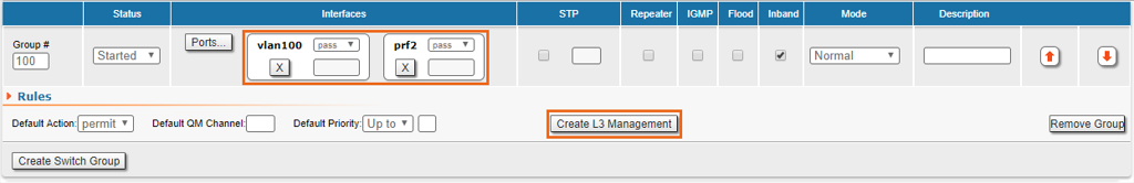
- Step 2: create switch group 100 on InfiMUX1, add vlan100 and prf2 interfaces, provide same settings on InfiMUX2, but add only prf2 interface to switch group. Create switch group 100 on each wireless device and add only rf* interface.
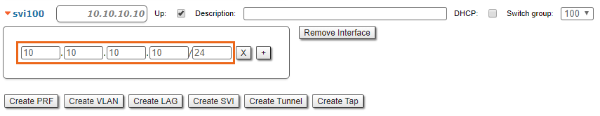
- Step 3: for all devices in created switching group settings click the "Create L3 management" button, the svi100 interface will be created automatically.
- Step 4: for all devices, go to the "Basic Settings → Network settings" section and assign an IP address to the svi100 interface.
Data traffic transmission
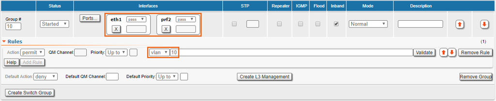
It is necessary to create switch groups with number 10 on InfiMUX1 and InfiMUX2, since these devices are gateways for user traffic between MINT and Ethernet. On wireless devices, switch groups for user data are not created, since they are transit devices within the MINT domain.
- Step 1: on InfiMUX, go to the "Basic Settings → MAC Switch" section and click the "Create switch group" button.
- Step 2: add eth1 and prf2 interfaces to created switch groups on both InfiMUX devices.
- Step 3: add rule "vlan 10" to created group.