Quanta 70: Installation and Configuration
Troubleshooting
account course progress
This lesson describes basic troubleshooting actions to be taken in case a problem occurs to the wireless link.
List of possible problems:
- No access to the local unit.
- Wireless link is not established.
- The wireless link is established, but there is no access to the remote device.
- The wireless link throughput is lower than expected.
- Common errors in configuration.
1.No access to the local unit
Checking the network infrastructure
Make sure there is connectivity between the control center and the device installation point. If the access is missing only to the Infinet device, further verification must be performed at the installation site.
LED indication
Check the network connectivity between the monitoring server and the local unit. If no connectivity appear, go on site to the local unit location. Check if it is powered on, power indicator has blue color, wired connection: red – 10 Mbps, yellow – 100 Mbps, green – 1000 Mbps. If there is no power please check the AC power supply, the Ethernet cables and connector.
Access to the unit recovery
If the management of the unit is completely lost (of the local and/or the remote one), the ERConsole recovery procedure should be used. ERConsole is a software application created to recover or add a new IP address to the Infinet Wireless units. Additionally, the ERConsole can be used to reset the Infinet Wireless units to the factory default configuration.
Software requirements::
- ERConsole: ftp://ftp.infinet.ru/pub/Utils/EmergenceRepairConsole/ERConsole.zip.
- Java Runtime Environment: http://www.java.com/en/download/.
It is recommended to turn off any anti-virus or firewall running on your computer and to turn off all the network interfaces, except the Ethernet interface connected to the same broadcast subnet as the Infinet Wireless unit. If no device can be discovered by ERConsole, turn on the firewall, and add an UDP connection port 10009 as an exception.
We also recommend to use a simple unmanaged switch as intermediary unit between your PC and the InfiNet Wireless unit. It is essential to reboot the Infinet Wireless unit each time in order to activate the Emergency Repair Protocol on the unit, therefore the switch would prevent your PC Ethernet interface from flapping up and down. Using Cisco Catalyst switches for unit recovery is not recommended due to a known issue port mode negotiation delay.
NOTE
ERConsole and InfiNet Wireless units exchange information only during the bootup process, therefore each time you need to read the units IP address, to add a new IP or to restore to the default configuration, the InfiNet Wireless unit should be rebooted.
Access to the unit
If you have lost management to your unit, proceed as follows:
- Run the ERConsole.
- Turn off the unit and then turn it on in a few seconds.
- Wait for 30 seconds and the ERConsole screen should receive update from the unit. The serial number, number of unit reset cycles ("Sequence" field), IP address, network mask and MAC adress will be displayed on the screen.
Further recovery depends on whether the IP-address is assigned or not to the unit.
IP address and net mask are assigned
Configure on your PC an IP belonging to the same network and connect to the unit in order to perform the modifications and checking required. If there is no IP, displayed (0.0.0.0), proceed with the next step.
IP address and net mask are not assigned
- Click the "+" button in the ERConsole application and a new window will appear.
- In the "New task" window, set the additional IP address and network mask, then click "OK".
- Turn off and on the unit. Wait for 30 seconds until the IP is assigned.
- Add an IP address from the same network subnet to your PC and access the unit. ERConsole will not show newly assigned IP address.
- Login to the unit using the new IP. Do not reboot the unit until the new configuration has been saved because the additional IP address is temporary.
Restore to the factory default settings
In case you need to restore your unit to the factory default settings, proceed as follows.
NOTE
If the management of the unit is lost due to unknown user name or password it can be restored using factory password. Enter the device serial number to the "Login" field and factory password - to the "Password" field.
- Obtain the factory password. In order to do this, please contact the distributor through whom the unit was purchased, or in case purchasing the unit directly in InfiNet Wireless, send a request to the InfiNet Wireless support team. The request must include the unit serial number and the value of "Sequence" field (if it's non-zero).
- Obtain the unit IP address using the ERConsole as described in the section above.
- Click on the "+" button in the ERConsole application and a new window will appear.
- Select "Reset configuration" option and enter the factory password to the "Factory password" field, then click "OK". The password must be entered at the same format as it has been got from the distributor or IW support team (with the gaps).
- Turn off and on the unit and then wait for about 30 seconds.
- The unit will start in a special emergency mode with the IP address 10.10.10.1 and mask 255.255.255.0.
- Login to the unit and use "Restore factory settings" button on the "Maintenance" section to switch off emergency mode.
- Set new login and password, then save the configuration and restart the unit.
If the local connection is allowed, after the authentication step in web interface, check the operational status of the wired port. Enable the port if found disabled, check the connectivity matrix and VLAN settings if used. Reboot the unit at the "Maintenance" section.
Checking the wired interface state
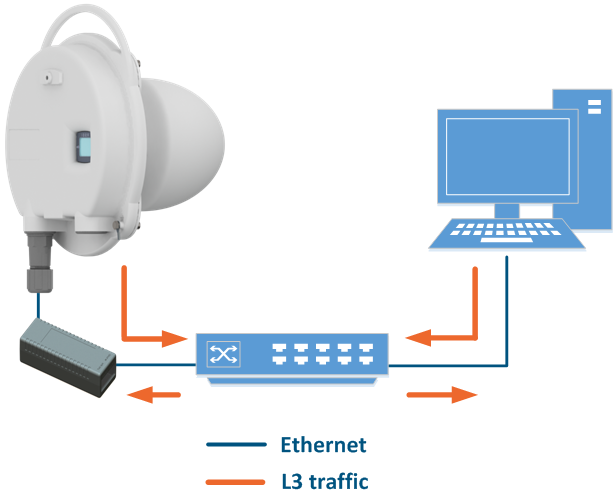
If you were able to access the device by connecting directly, try to determine the possible reason for the unavailability through the network. Pay attention to the wired interface statistics.
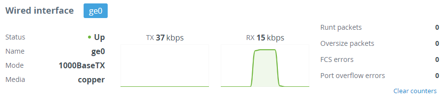
In the "Wired interface" section, you can monitor the wired interface status and its traffic load for reception and transmission. The wired interface statistics is on the right side and can be reset by clicking the "Clear counters" button. Pay attention to the FCS errors number which indicate a violation of data integrity during transmission over the wired segment. Also, the problem can be caused by a queue (port) overflow or inappropriate frame size (runt and oversize).
Note
The FCS errors counter can increase due to the following reasons:
- The device connection is performed using inappropriate cable. We strongly recommend to use FTP Cat5e cable with outside diameter not exceed 7 mm.
- A shielded RJ-45 connector is used from the outdoor unit side. Make sure RJ-45 connectors are installed in the correct order. The shielded connector must be installed on the power supply side, the standard RJ-45 must be installed on the wireless device end.
- The device is grounded incorrectly, make sure the device installation complies with the recommendations specified in the "Grounding and Lightning Protection" article.
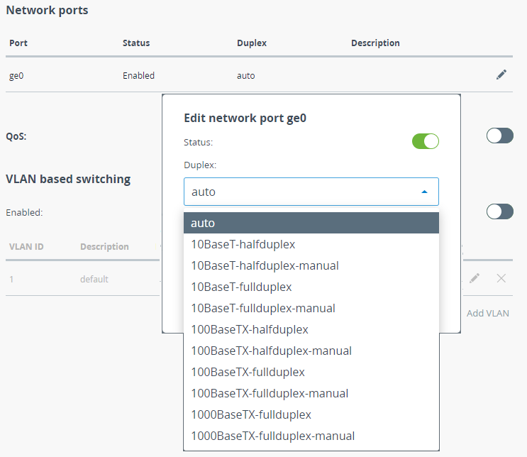
Pay attention to the duplex mode on the network devices connected to the wireless bridge. The duplex mode can be changed in the "Switch" - "Network Ports" section. We recommend setting the autonegotiation mode provided by the Ethernet standard. The problem can occur while connecting two devices with different duplex settings. For example, if one device has the autonegotiation mode, and the other - fixed full duplex mode.
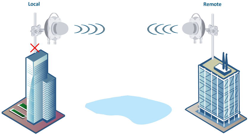
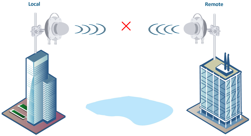
2. No access to the remote unit
The section describes how to test the link when there are no radio communication and no access to the remote unit, but there is access to the local unit.
Check the weather conditions
The 70,5-76 GHz frequency range is sensible to the weather condition changes, rain, snow and fog can significantly affect the wireless connection quality.
Pre-configuration in the lab
Before installing the devices on site, we recommend to configure the basic parameters in the lab and to make sure that the link is establishing. Step-by-step instructions for a wireless link configuration are given in the "4. Link Pre-configuration in the lab" lesson.
Note
During the configuration of the devices in a lab, take into account the following requirements:
- Make sure the devices are positioned no closer than 12 meters from each other and are not directed at each other in order to prevent radio modules damage.
- A minimum transmit output power must be set.
- The failure or damage of the device's radio module in case of disregarding these requirements is not covered by warranty.
Checking the radio parameters
If the wireless link is not establishing in lab conditions, make sure that the radio parameters are set to the values determined during the planning stage. The correct configuration of the device can be obtained using the Configuration Generator tool found on the IW Academy website. To establish a wireless link, one device must be configured as Master, the second (or all subscribers of the base station in the point-to-multipoint topology) as Slave. The following parameters must be identical on both devices:
- Frequency.
- Frame length.
- Access key.
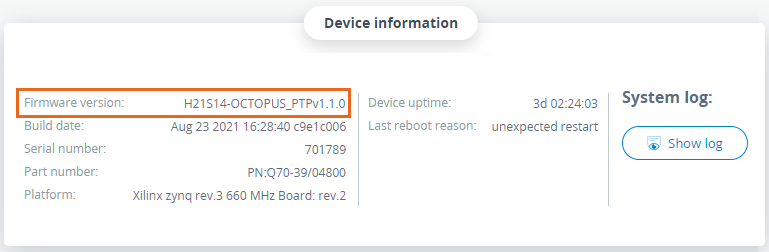
Checking the firmware version
In the "Maintenance" section, make sure that the same firmware version is installed on both devices. The latest software versions can be downloaded from the official Infinet FTP server.
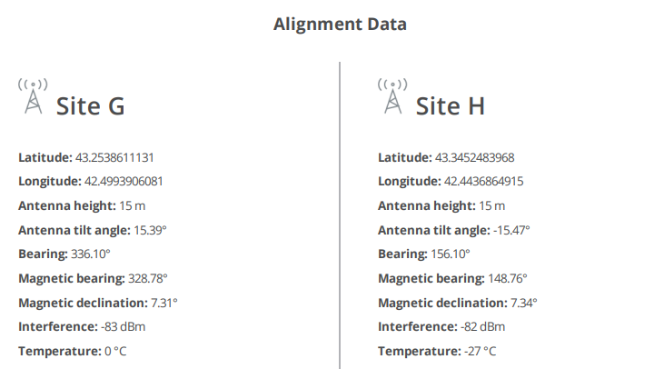
Path profile check
If the wireless link is down after previous steps, check the antennas alliagnment with two teams working simultaneously, one at the remote side and the other one at the local side. Also,redo the radio planning to avoid the situation when coordinates at the initial radio planning stage is different from the current location: huge interferences on the working set of frequencies, Fresnel zone obstruction are possible reasons why the wireless link cannot be established, etc.
Checking the installation requirements
Check if the suspension height, azimuth and elevation of the antenna match with the values obtained from InfiPLANNER. Make sure that the obstacles on the path profile are not higher than those specified during the planning phase.
3. The wireless link is established, but there is no access to the remote device
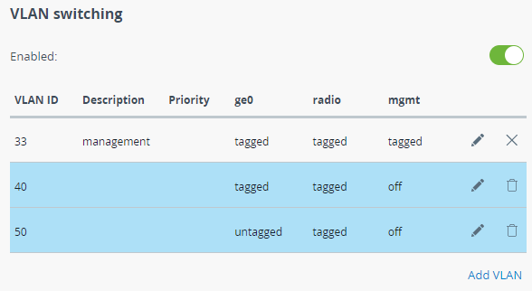
Checking the switch settings on the local device
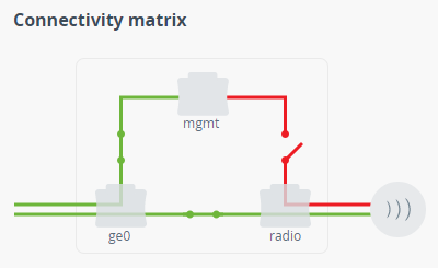
In the "Switch" section of the web interface, make sure the VLAN-based switching settings are configured in accordance with the network architecture. Make sure the connectivity between the "ge0" and "radio" interfaces is enabled.
Checking the switch settings on the remote device
Further diagnostics should be performed at the device installation site. Try to access the device directly using the ERConsole utility.
When accessing the web interface, in the "Switch" section, make sure the VLAN-based switching settings are configured in accordance with the network architecture. Make sure the connectivity between the "ge0", "radio" and "mgmt" interfaces is enabled in a connectivity matrix.
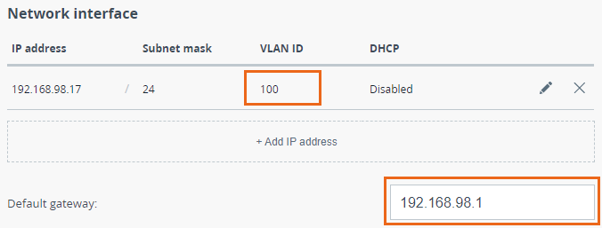
In the "Network" section, make sure the correct VLAN ID is assigned to the management IP address and the default gateway is configured in accordance with network architecture.
4. Expected throughput is not met
The wireless link is established but the capacity is less than expected.
Check the weather conditions
The 70,5-76 GHz frequency range is sensible to the weather condition changes, rain, snow and fog can significantly affect the wireless connection quality.
Local and remote units settings check
Login to both units via web interface, check the availability of the new firmware version. If a newer firmware version is available, proceed with the firmware upgrade in order to benefit of the latest radio features and improvements.
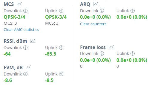
Proceed to the "Radio" section and check the frame length value, if it is too small, try to increase it. Perform the antenna alignment with built-in tool especially in case of low RSSI and EVM values.
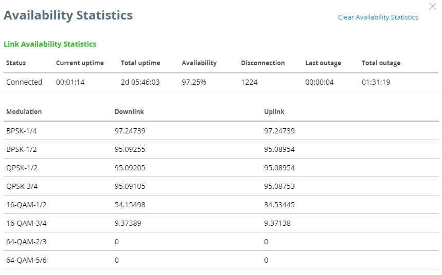
Availability statistics
To analyze the wireless link availability time, proceed to the corresponding statistics in the "Dashboard" - "Availability statistics" of web interface. The opened window displays the link operation statistics for each modulation.
5. Common errors in configuration
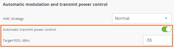
Automatic transmit power control
Enable the automatic transmit power control (ATPC) in order to increase the operational life of the devices. Set the "Target RSSI" parameter to values from -40 to -60 dBm.
Frame length
Make sure the selected frame size ensures the best performance for your wireless system. A short frame will transmit less payload than a long one, however it ensures a smaller delay.