Quanta 70: Installation and Configuration
Installation Prerequisites
account course progress
Packing List
Before the installation, please make sure you have all necessary parts and accessories.
Q70-39 packing list
- Outdoor unit (ODU).
- Power supply.
- Cable gland for Optical cable.
- Cable gland for Ethernet cable
- Shielded RJ-45 connector.
- Unshielded RJ-45 connector.
- RJ-45 plug cap.
- Mounting kit - universal assembling kit for mounting the ODU on standard pole, wall or thick pipe (vertical/horizontal).
- Power cord - the model depends on the region, according to the Purchase Order.
Q70-50 packing list
- Outdoor unit (ODU).
- Power supply.
- Cable gland for Optical cable.
- Cable gland for Ethernet cable
- Shielded RJ-45 connector.
- Unshielded RJ-45 connector.
- RJ-45 plug cap.
- Mounting kit assembled.
- Bolt M8x165 (x4).
- Bolt M8x50 (x2).
- Washer 8 flat (x6).
- Washer 8 spring (x6).
- Nut M8 (x6).
- Bracer (x2).
- Power cord - the model depends on the region, according to the Purchase Order.
Cable Gland Assembly
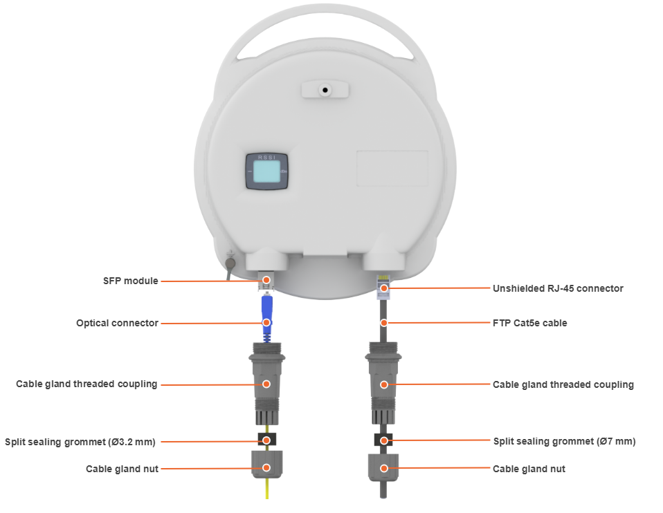
Cable Gland Assembly for RJ-45 connector
Required components:
- Unshielded RJ-45 connector.
- Shielded RJ-45 connector.
- FTP Cat5e cable.
- Cable gland:
- Cable gland nut.
- Split sealing grommet (with inner diameter 7 mm).
- Cable gland threaded coupling.
- Crimping tool for RJ-45 connector.
NOTE
The outside diameter value of the FTP Cat5e cable should not exceed 7 mm.
Cable gland can be assembled on pre-crimped cable.
Assemble procedure
In order to ensure that the device case remains sealed under any environmental conditions follow the assemble procedure:
- Step 1: Crimp the standard RJ-45 connector onto the cable using crimping tool. Pin-out scheme: T568B wiring standard.
NOTE
Do not use the shielded RJ-45 connector on this end of the cable as it should be attached on the power supply unit end.
Make sure that the RJ-45 connector is well-crimped. A loose connector can damage the device. Please note that such damage is not covered by the warranty.
- Step 2: Assemble cable gland nut, the split sealing grommet and the cable gland threaded coupling onto the pre-terminated cable as shown on the figure below.
- Step 3: Insert the split sealing grommet into the cable gland threaded coupling.
- Step 4: Insert the RJ-45 connector into the device socket until you hear a click.
- Step 5: Screw the cable gland threaded coupling into the port and tighten it. Do not apply excessive force.
- Step 6: Tighten the cable gland nut (4). Do not apply excessive force.
Cable Gland Assembly for Optical Cable
Required components are listed below.
- Optical cable.
- Optical connector.
- SFP module.
- Cable gland:
- Cable gland nut.
- Split sealing grommet (with inner diameter 3.2 mm).
- Cable gland threaded coupling.
Assemble procedure
- Step 1: Put the cable gland nut, the split sealing grommet and cable gland threaded coupling onto the pre-terminated optical cable as shown on the figure below.
- Step 2: Insert the split sealing grommet into the cable gland threaded coupling.
- Step 3: Set the SFP-module into the socket until you hear a click.
- Step 4: Insert the optical connector into the SFP module.
- Step 5: Screw the cable gland threaded coupling into the port and tighten it.
- Step 6: Tighten the cable gland nut. Do not apply excessive force.
NOTE
In order to disassemble SFP, please disconnect the optical cable, pull the clip of the SFP-module and withdraw the SFP-module from the slot.
SFP module is not included into the packing list.
Mounting Kit
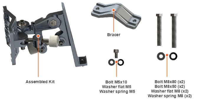
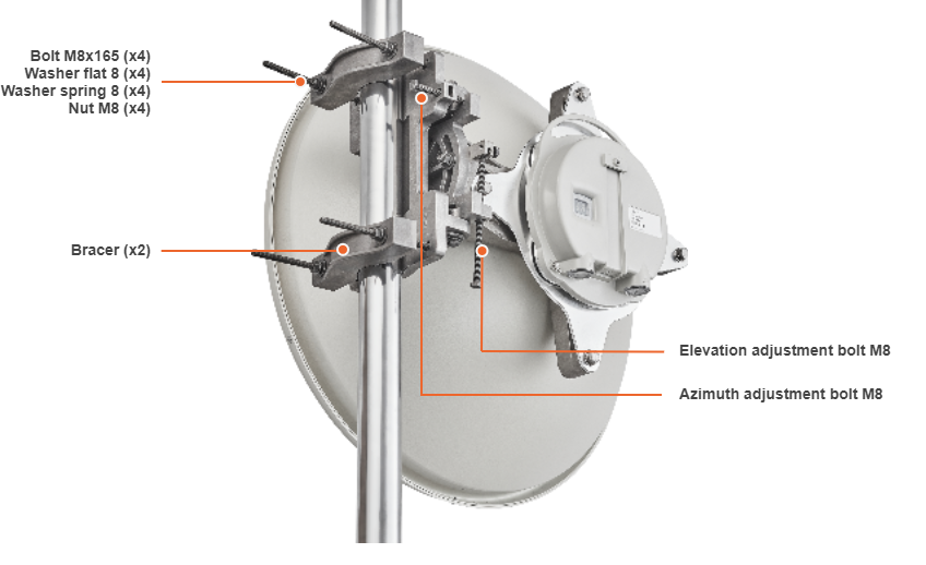
MONT-KIT-85PW
High-precision MONT-KIT-85PW is supplied with Q70-39 model by default. It allows to make reliable and easy installation of the unit with two-axis adjustment.
Packing List
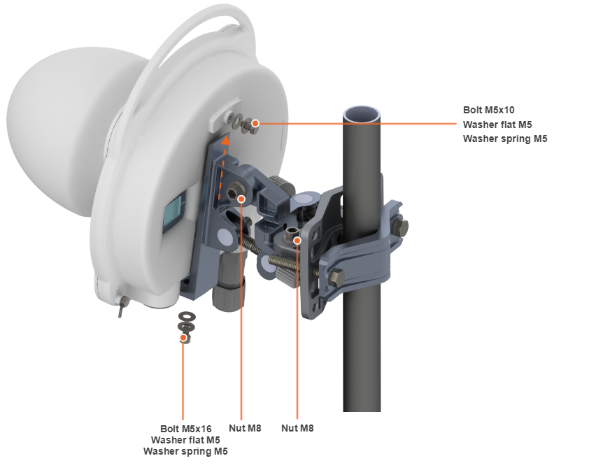
Assemble Procedure
Step 1: Tighten the Assembled kit and Bracer to the pole using bolt M8, washer flat M8 and washer spring M8.
- Bolt M8x50 - used for installation on pole with Ø 30 ... Ø 55 mm.
- Bolt M8x80 - used for installation on pole with Ø 55 ... Ø 85 mm.
Step 2: Insert and tighten the Assembled kit on the back side of the device using bolts M5x10, M5x16, washers flat M5 and washers spring M5.
Step 3: Perform required antenna alignment using adjustment knobs and then tighten nuts M8.
NOTE
M8 nuts are pre-tightened at the manufacturing facility in a position that allows the device to be adjusted using the adjustment knobs and ensures that the wireless device does not shift during the final nuts tighten.
If further adjustment is required, weaken the nuts M8 on about 15 degrees. Do not adjust the knobs without weaken the nuts first.
Mounting is carried out on a pole with a diameter 30 ... 85 mm. There are also possible options for mounting on a wall or pole with a diameter more than 85 mm.
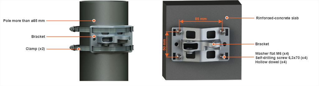
NOTE
Clamps and other optional fasteners are not included in the Mounting kit MONT-KIT-85PW.
Mounting kit for Q70-50
Q70-50 model installation is performed using mounting kit that is supplied by default. Install the device according to the schemes and procedure below.
Assemble Procedure
Scheme#1
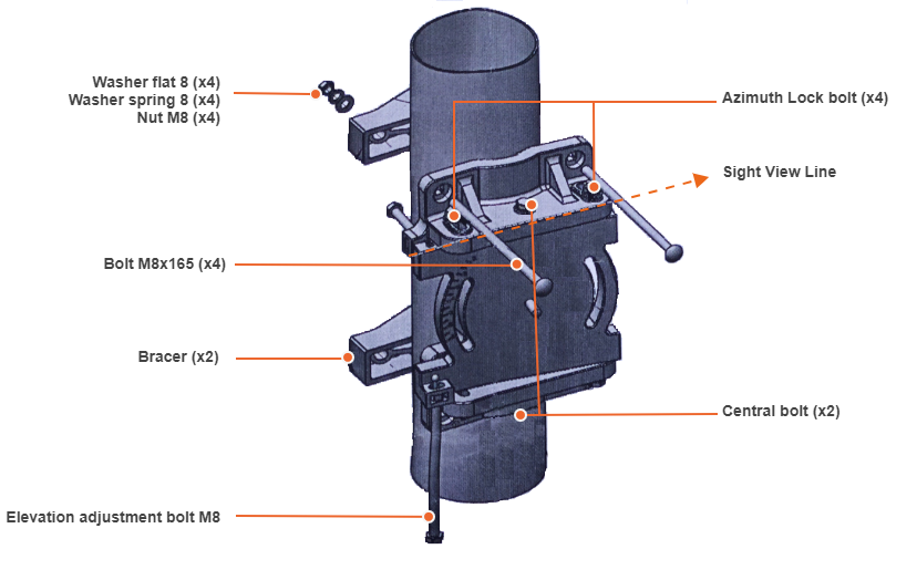
Step 1: Put Bolts M8x165 to its sockets, attach to the mast and assemble Bracers on the bolts. Put the Nuts M8 and Washers 8 (flat and spring) on the bolt without fastening.
Step 2: Roughly aim the mounting kit with the sight view line towards the target.
Step 3: Use tightening torque of 16 Nm on the Nuts of Bolts M8x165 with 12.7 mm open end, or deep socket wrench. Tool's length should not exceed 20 cm.
Step 4: Use initial tightening torque of 10 Nm on Central bolts (x2) and Azimuth Lock bolts (x4). Use 12.7 mm open end, or deep socket wrench.
Step 5: Screw the Elevation adjustment bolt to its position shown in the scheme#1.
Scheme#2
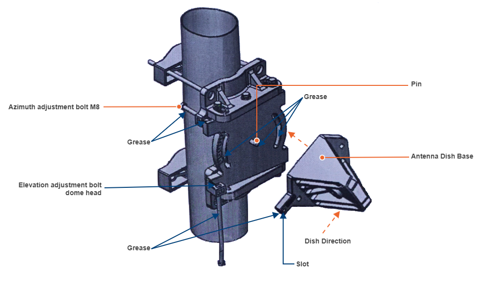
Step 6: Use grease on marked recommended places (see scheme#2).
Step 7: Attach Antenna Dish Base to Mounting kit Pin. Make sure Dish is pointing to target.
Step 8: Slide Elevation adjustment bolt dome head into it's slot on Antenna Dish Base.
Scheme#3
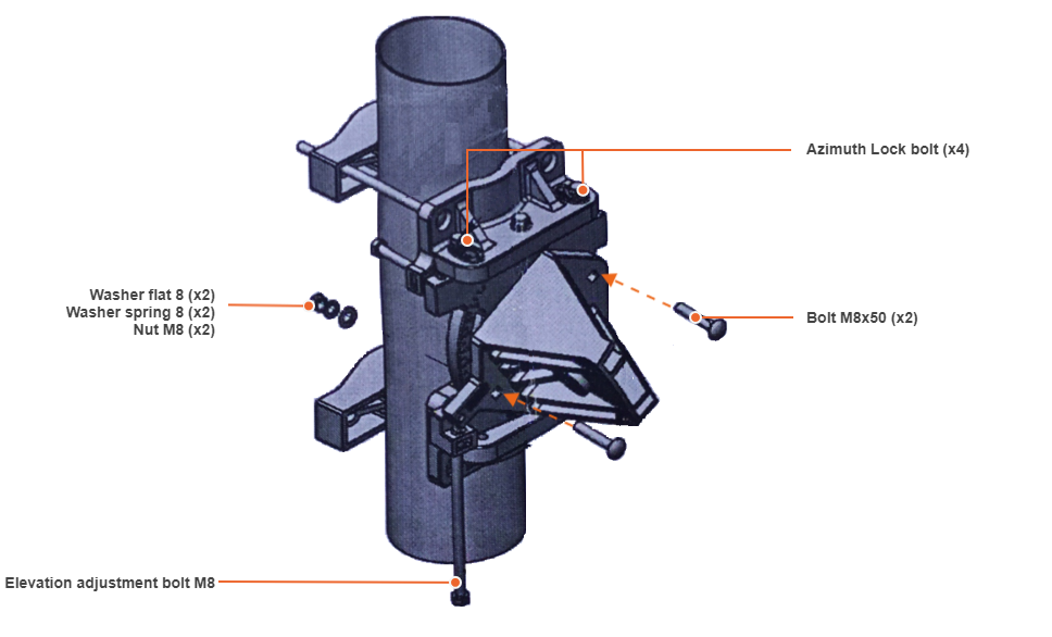
Step 9: Put Bolts M8x50 into their sockets and lock with Nuts M8 and Washers 8 (flat and spring) to initial tightening torque of 10 Nm.
Step 10: Screw Elevation adjustment bolt upward up to antenna horizontal position.
Scheme#4
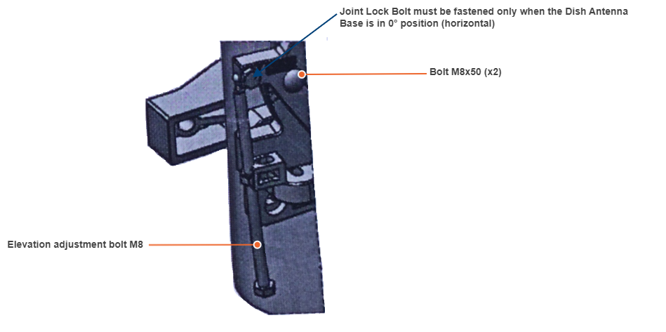
Step 11: Screw Joint Lock bolts lock.
Step 12: All the time keep Elevation adjustment bolt in parallel to the mast.
Step 13: After fine adjustment use tightening lock torque of 16 Nm on Azimuth Lock bolts and on Central bolts. Use tightening lock torque of 16 Nm on the Nuts of bolts M8x50. Use 12.7 mm open end, or deep socket wrench.
Step 14: After assembly verify that the drain plug located on the dish faces up, and the drain hole faces down.
Step 15: Adjustment bolts (Elevation and Azimuth) must be greased at all time.