Quanta 5 / Quanta 6: Installation and Configuration
Installation Prerequisites
account course progress
Packing List
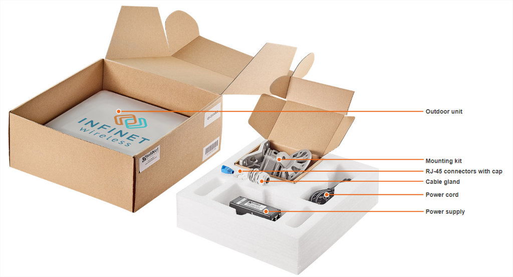
Before the installation, please make sure you have all necessary parts and accessories.
Q5-28, Q5-25, Q5-23, Q5-E, Q6-28, Q6-25, Q6-E packing list
- Outdoor unit (ODU).
- Power supply.
- Cable gland - 2 pcs.
- Shielded RJ-45 connector.
- Unshielded RJ-45 connector.
- Mounting kit - universal assembling kit for mounting the ODU on standard pole, wall or thick pipe (vertical/horizontal).
- Power cord - the model depends on the region, according to the Purchase Order.
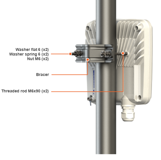
Q5-18, Q6-18 packing list
- Outdoor unit (ODU).
- Power supply.
- Cable gland.
- Shielded RJ-45 connector.
- Unshielded RJ-45 connector.
- Power cord - the model depends on the region, according to the Purchase Order.
- Nut M6 DIN 934 A4 (x2).
- Washer 6 flat (x2).
- Washer 6 spring 6 (х2).
- Threaded rod M6x90 (х2).
- Bracer.
Cable Gland Assembly
Required components
- Unshielded RJ-45 connector.
- Shielded RJ-45 connector.
- FTP Cat5e cable.
- Cable gland:
- Cable sealing nut.
- Cable sealing grommet with rubber seal.
- Cable gland case.
- Crimping tool for RJ-45 connector.
NOTE
The outside diameter value of the FTP Cat5e cable should not exceed 7 mm.
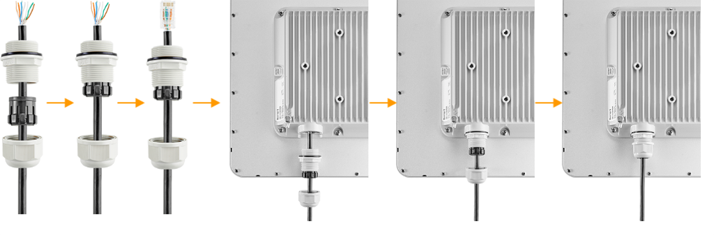
Assembly process
- Step 1: Insert the rubber seal into the sealing grommet.
- Step 2: Put the cable gland components onto the pre-terminated cable.
- Step 3: Insert the sealing grommet into the gland case.
- Step 4: Crimp the unshielded RJ-45 connector onto the cable using the crimping tool in accordance with T568B standart.
NOTE
Make sure that the RJ-45 connector is well-crimped. A loose connector can damage the device. Please note that such damage is not covered by the warranty. Use the shielded RJ-45 connector and connector cap on the power supply end of the cable.
- Step 5: Insert the connector into the socket until you hear a click.
- Step 6: Screw the cable gland case into the port and tighten it. Do not apply excessive force.
- Step 7: Tighten the cable sealing nut. Do not apply excessive force.
Cable Gland Assembly for Optical Cable
Required components are listed below.
- Optical cable.
- Optical connector.
- SFP module.
- Cable gland:
- Cable gland nut.
- Split sealing grommet (with inner diameter 3.2 mm).
- Cable gland threaded coupling.
Assemble procedure
- Step 1: Put the cable gland nut, the split sealing grommet and cable gland threaded coupling onto the pre-terminated optical cable as shown on the figure below.
- Step 2: Insert the split sealing grommet into the cable gland threaded coupling.
- Step 3: Set the SFP module into the socket until you hear a click.
- Step 4: Insert the optical connector into the SFP module.
- Step 5: Screw the cable gland threaded coupling into the port and tighten it.
- Step 6: Tighten the cable gland nut. Do not apply excessive force.
Mounting Kit
Q5-28, Q5-25, Q5-23, Q5-E, Q6-28, Q6-25, Q6-E mounting
MONT-KIT-85 (MONT-KIT-85S for antennas with gain of 28dBi) is supplied with device by default. It allows to make reliable and easy installation of the unit with two-axis adjustment. Assemble the Mounting kit according to the scheme below. The nut must be tightened until the spring washer clicks, without over-tightening.
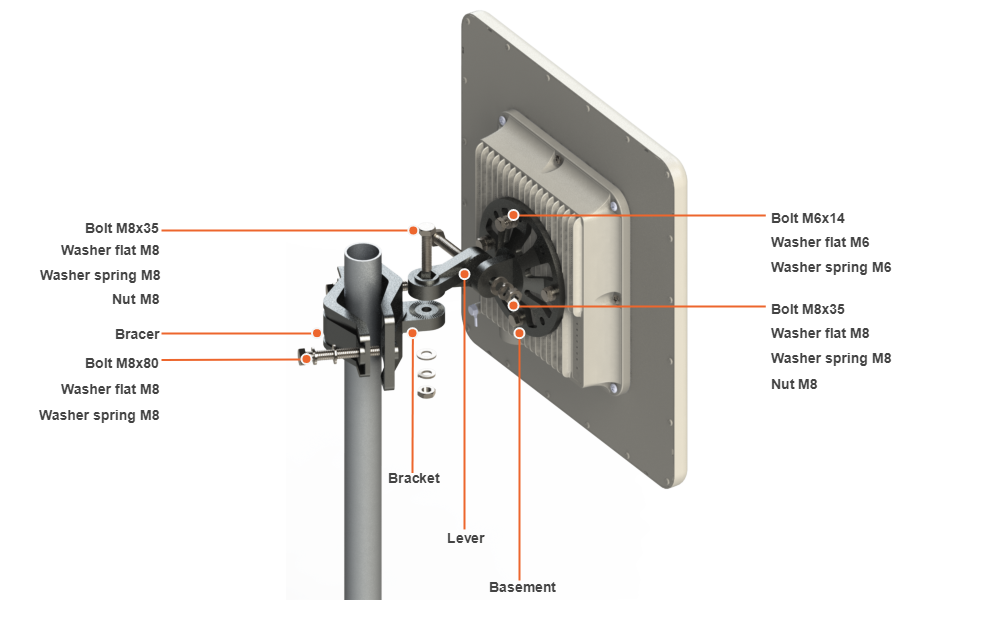
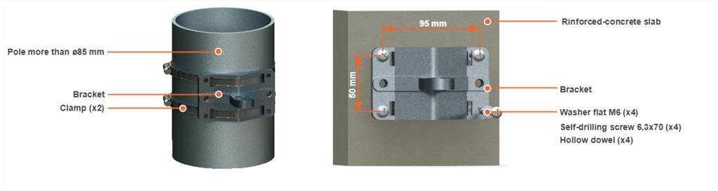
Mounting is carried out on a pole with a diameter 30-85 mm. There are also possible options for mounting on a wall or pole with a diameter more than 85 mm.
NOTE
Clamps and other optional fasteners are not included in the Mounting kit MONT-KIT-85.
Q5-18, Q6-18 mounting
Q5-18, Q6-18 models installation is performed using bracer and threaded rod M6x90 that s supplied by default. Install the device according to the scheme below. The nut must be tightened until the spring washer clicks, without over-tightening.