Quanta 5 / Quanta 6: Installation and Configuration
Mounting and Antenna Alignment
account course progress
Pre-installation
Reqiered tools
- Screwdriwer set.
- Pliers / pipe wrench.
- Wrench set.
Additional equipment
- GPS receiver.
- High magnification binoculars.
Before mounting the equipment in an outdoor environment, please make sure that:
- You acknowledge the regulations imposed by the Regulatory Authority for Communications in your country for the radio spectrum to be used.
- You chose known locations for the installation of the links; although Infinet Wireless devices can also operate in Near-LoS or Non-LoS conditions, to achieve the best performance, it's highly recommended to install the link in locations where Clear-Line-of-Site and clear channels are available.
- You performed link planning using the InfiPLANNER tool (https://infiplanner.infinetwireless.com) to determine the link path profiles, radio equipment placement requirements, etc.
Installation Procedure
- In case of device with external antenna. Prepare RF cables of the required length, recommended maximal length is 1 meter. Install and isolate the connectors on the RF cable.
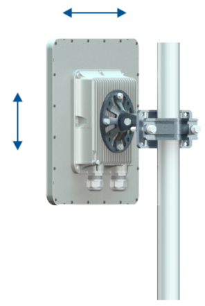
- Install ODU connector facing down using the MONT-KIT-85. Do not tighten the fasteners to the end until the alignment is completed.
- Connect the Cat5e FTP cable with the cable gland to ODU.
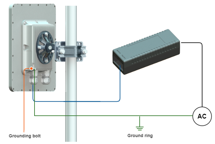
- Perform ODU grounding.
- Lay the Cat5e FTP cable from ODU to the power supply.
- Connect the Cat5e FTP cable with a shielded connector covered by a cap to the "OUT" port of the power supply, having previously touched the power supply connector case with FTP cable connector case.
- Perform the power supply grounding.
- Connect the laptop using Cat5e FTP cable to the power supply "IN" port.
- Connect the power cord to the power supply and then to the power circuit.
NOTE
In order to prevent device damage make sure that antenna is connected to both N-type connectors with serviceable RF cables before switching on.
Make sure a small loop (at least 10 cable diameters) is provided before the Cat5e FTP cable enter into the building.
Grounding and Lightning Protection
General recommendations for lightning protection and grounding:
- ODU should be placed on the pole at a height that is at least 1 meter below the top of the pole. In this case, there is a significant probability that the lightning strikes the pole and not the ODU. The pole should be properly grounded: connected to the building lightning protection circuit according to your local regulations.
- The device ground bolts must be connected to a ground ring.
- Shielded RJ-45 connector must be installed at the power supply cable end. Unshielded RJ-45 connector must be installed at the ODU end of the cable.
- The power supply IDU-CPE-G is grounded using a three-core power cord and a electric point with a grounding contact.
- AUX-ODU-LPU-G grounding is performed using grounding clamp.
- Antenna pole, wireless device and a lightning protector must be grounded to one ground ring. A good electrical connection should be provided in one or several places with a cable not less than 2.5 mm thick using connectors resistant to corrosion. The grounding system must be performed in accordance to local building standards.
- Special attention should be paid if the external antenna used is not DC-shorted. In this case, an additional lightning arrestor should be used between the antenna and ODU.
NOTE
Please note grounding cables should not be connected to the mast. All devices must use separate grounding cable that should be connected to the grounding circuit. The best scenario is when grounding cables are lined parallel to the Ethernet cable.
Grounding with AUX-ODU-LPU-L
AUX-ODU-LPU-L is an optional accessory which may be used to serve as a line protection unit for the ODU and for the indoor network equipment connected to the Ethernet port of the IDU. AUX-ODU-LPU-L should be properly assembled, mounted and grounded.
General recommendations for installations of lightning protection units:
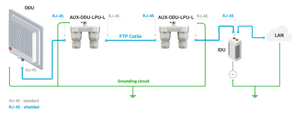
- Install the lightning protection unit on both ends of the cable to protect both the outdoor and the indoor unit. The purpose of the LPU at the top is to protect the ODU from a surge of lightning strike which can hit the long FTP cable run along the height of the pole or on the roof of the building. The purpose of the LPU at the bottom is to protect the IDU and customer equipment.
- Use the lightning protection unit to protect all circuits for signal transmission and power supply (video, audio, management signals, Ethernet, etc.)
- Regularly (especially before the periods with high thunderstorm activity) check the integrity of lightning protection units, grounding elements and bonding conductors.
Make sure to install the two LPU devices as shown in the scheme below.
AUX-ODU-LPU-L is installed on a mast, using clamp. Attach the grounding cable (min cross-section 2.5 mm2) to the case, using grounding bolt.
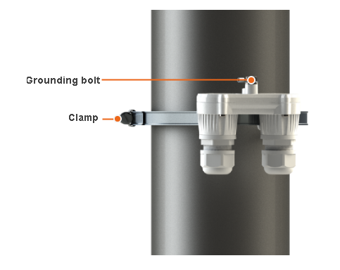
During AUX-ODU-LPU-L mounting it is necessary to provide a small loop of the FTP cable that should be below the cable gland. This ensures that water is not constantly channeled towards the connector. It will also serve as a cable compensation for the cable linear expansion as the temperature difference result.
Grounding with AUX-ODU-LPU-G
AUX-ODU-LPU-G – additional lightning protection device for outdoor using, compliant with GR-1089. Not included in standard packing list.
Installation principles:
- Check the integrity of lightning protection devices grounding elements and bonding conductors sometimes, especially before the thunderstorm season start.
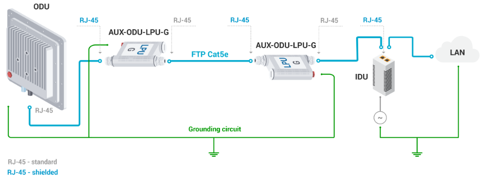
- For maximum protection of the wireless device, power supply and customer LAN devices, use two AUX-ODU-LPU-G lightning protection unit, connected as it is shown at scheme below.
- The purpose of the LPU at the top is to protect the wireless device from a surge of lightning strike which can hit the long FTP cable run along the height of the pole or on the roof of the building. The purpose of the LPU at the bottom is to protect the power supply and customer equipment.
- Install the first LPU as close as possible to the ODU, the second - to power supply.
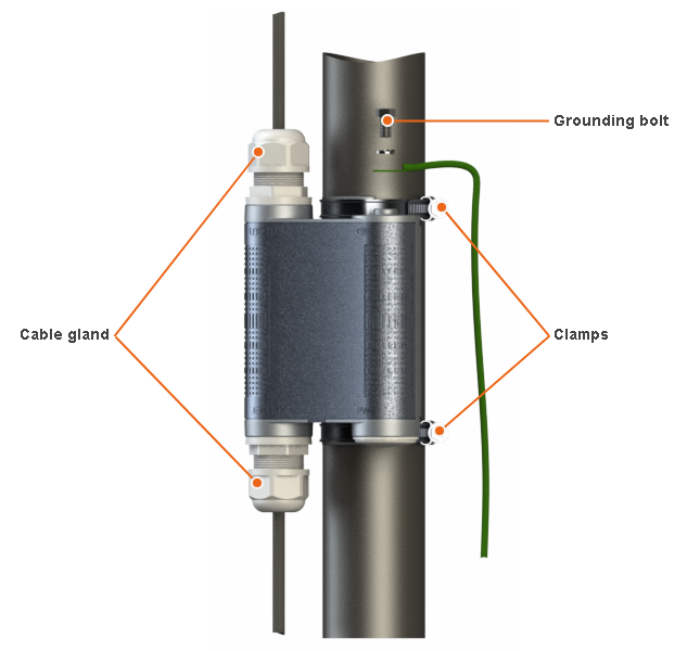
AUX-ODU-LPU-G can be installed on a pole, using hose clamps. Attach the grounding cable (min cross-section 2.5 mm2) to the case, using grounding bolt.
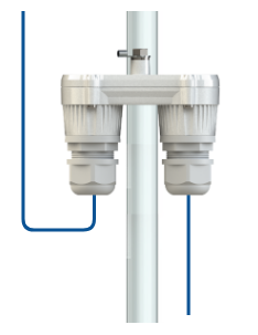
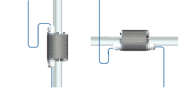
Make sure a small loop is provided during AUX-ODU-LPU-G devices installation. A loop must be below cable entry. The loop is necessary to make water (precipitation, condensate, etc.) flows along it. It will also make a cable compensator function for linear cable expansion in case of temperature differences.
Spectrum Scanning
The "Spectrum analyzer" section allows to perform a deep analysis of the radio emissions in the environment where the unit is placed. The unit scans the radio spectrum on frequencies available by grid. In order to obtain the information as accurate as possible, the scanning process may take a while.
NOTE
During the spectrum analyzer operation, the device will be inaccessible via radio interface.
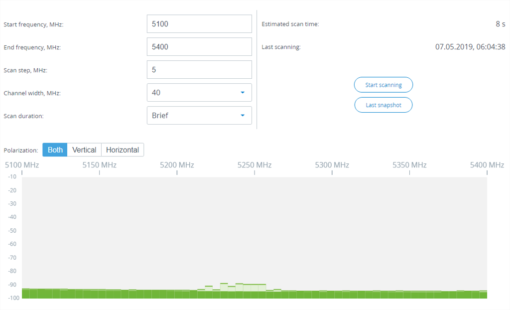
The following parameters of the spectrum analyzer can be configured:
- Start frequency - start scanning range frequency (measured in MHz);
- End frequency - end scanning range frequency (measured in MHz);
- Scan step - set frequency scanning step (measured in MHz). Recommended value for the most accurate scan results - 1 MHz;
- Channel width - frequency channel width (measured in MHz);
- Scan duration - full or brief scanning mode. Estimated scan time will be displayed in accordance with parameters set.
Usually spectrum scan is performed at the remote unit on the other side of the wireless link. During a spectrum scan at such a unit (accessible via the RF interface), connection to this unit will be lost for a scan time. Click the "Last Snapshot" button to view scan results when the connection will be restored.
During a spectrum scan at the local device, signal from the remote device will be displayed in the scan results. We recomend to turn off remote device radio interface to assess the situation in its absence. Otherwise, you will constantly see the noise generated by the remote device at the operating frequency.
Alignment
General recommendations:
- It is recommended to have two teams prepared for alignment procedure, each team with at least two members: one should take the signal readings and communicate with the remote end, the other should manipulate the antenna.
- For rough alignment use the azimuth, elevation angle and suspension height from InfiPLANNER report.
NOTE
For devices with an integrated antenna 18 dBi, the mounting kit allows alignment only in the horizontal plane.
- On the device case there is a scale indicating the received signal level. The more often indicator flashes, the better quality of the connection. Blinking indicator shows an intermediate state, the more often indicator is blinking, the higher the connection level.
- For more accurate alignment, use the alignment tool built into the device web interface.
- After the initial alignment, the device at the remote side must be fixed. Firstly, the alignment is performed for one device, then for another.
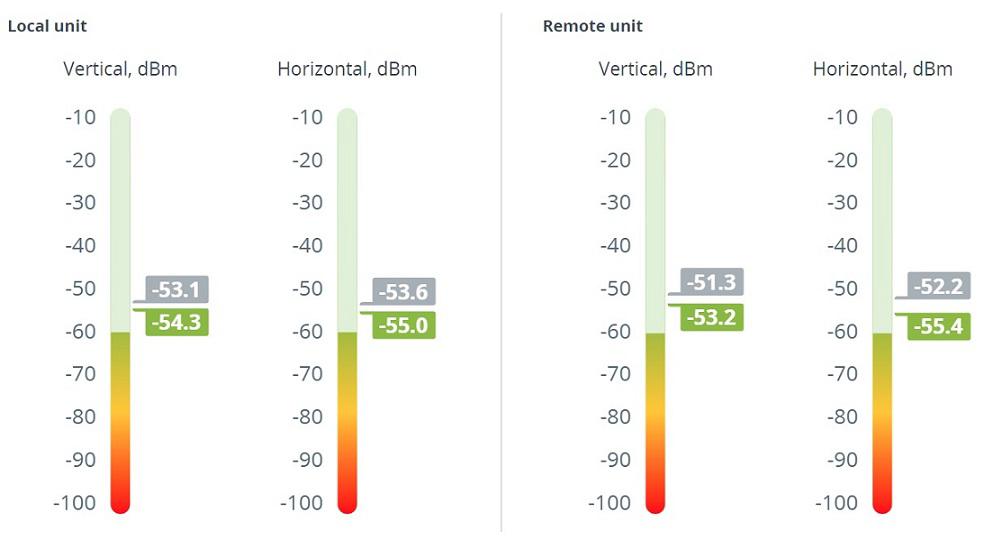
Alignment tool
Use the Alignment tool to point and optimize the antenna in the direction of maximum link signal. The built-in graphical antenna alignment tool displays the signal levels for both devices and both polarizations, this makes an alignment process fast and accurate.
A green marker indicates the current signal level. To achieve the best performance, this marker should be as close as possible to the gray area values, which displays the maximum calculated value possible for this link. A gray marker indicates the maximum value that was reached on this channel.