Quanta 5 / Quanta 6: Installation and Configuration
Settings
account course progress
Quanta 5 / Quanta 6 web interface is an intuitive and a sufficient tool for configuring and monitoring the link status. Essential tools such as antenna alignment and spectrum analyzer are included to make configuration and troubleshooting more efficient. Automatic mechanisms such as automatic frequency selection and automatic transmit power control optimize the link for maximum performance even in areas with high interference.
1. Access to the device
Network Settings
By default wireless device has IP address 10.10.10.1 with 255.255.255.0 network mask. The workstation used to perform initial configuration must have an IP address from the same subnet.
Login and Password
By default no login or password are set, use any letters or numbers for initial authentication.
Web Interface
Navigation in the web interface is performed using the side menu, which includes the following sections:
- Dashboard.
- Settings.
- Service.
Dashboard
This section displays the information on the wired and wireless connections state updated in real time and statistics since the last reboot. For detailed description of the parameters proceed to the "9. Diagnostics" lesson.
2. Applying changes
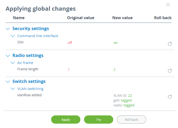
To make changes in the device configuration click the "Changes" button in the upper right corner of the web interface.
The "Applying global changes" window contains a table of parameters whose values have been changed by the user. If you want to undo one change, click the "Roll back" button near the entry. If you need to undo all changes, use the "Roll back" button at the bottom of the window. Changes will be saved to the device configuration by clicking the "Apply" button.
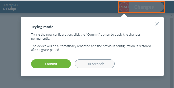
To apply the configuration safely, use the "Try" button. In this case, the previous configuration will be restored after 180 seconds automatically if changes will not be confirmed or test period extended by the administrator.
3. Settings
General
The section is designed to configure the basic system parameters of the device.
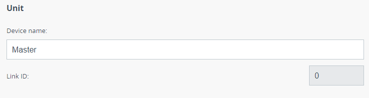
Unit
Configure the device name for easy identification. Can be an arbitrary set of characters. Is used for easy device identification by the network administrator, is displayed in the web interface in the "Dashboard" section.
Link ID allows to avoid connecting to wrong devices in case of several adjacent links. Must be the same at both sides of the link.
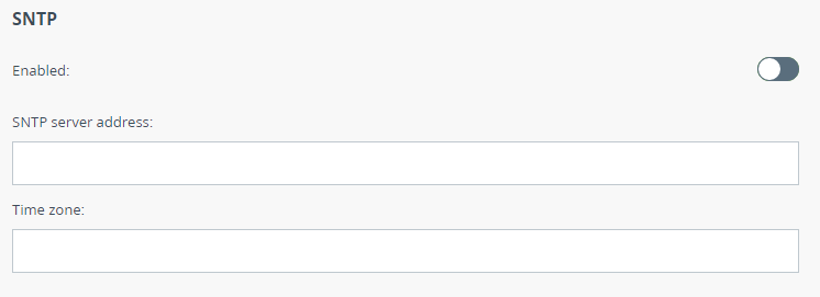
SNTP
To ensure correct time settings, for example, in the system log, SNTP should be started by enabling corresponding flag.
Set the SNTP server IP address, make sure the device has network access to the SNTP server.
Set the time zone of the device installation in the POSIX format. For example: GMT +5.
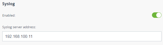
Syslog
To allow syslog data transmission to the server using the "syslog" protocol enable corresponding flag.
Specify the syslog server IP address where data should be transmitted.
Secutity
This section allows to configure device access and security settings.
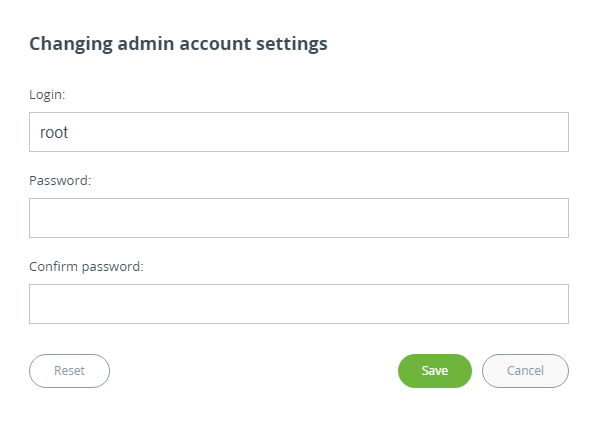
Administrator access
We strongly recommend to set a login and password after the first access to the device. In order to do this click the "Change admin password" button and enter new Login and Password.
Click the "Reset" button to return the access settings to default.
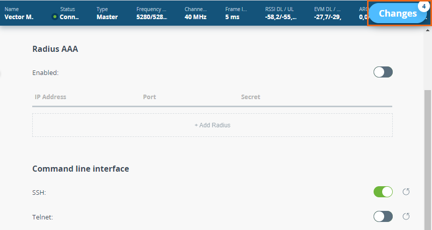
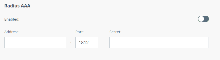
Radius AAA
The device can be accessed through a remote RADIUS server. To configure access, enable the corresponding flag and click the "Add Radius" button.
Specify the Radius server data: IP address, port and secret password.
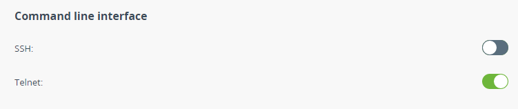
Command line interface
Use the corresponding flags to enable / disable remote management of the device by command line via Telnet and SSH protocols.
The Secure Shell (SSH) protocol provides secure remote management of network devices. Its functionality is similar to the Telnet protocol, but unlike Telnet, SSH encodes all protocol messages, including transmitted passwords. Only Telnet access is enabled by default.
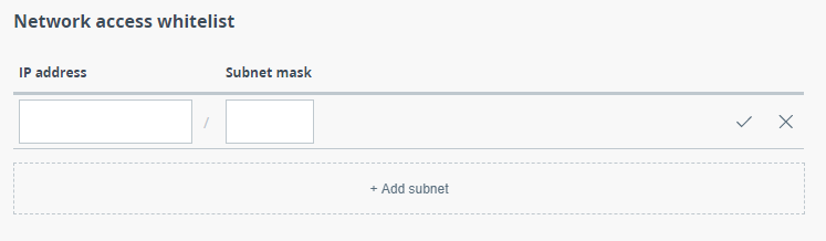
Network access
Access to the device can be limited to a list of subnets. To make restrictions, add a new entry for each subnet from which access should be allowed, and specify the IP address and Subnet mask.
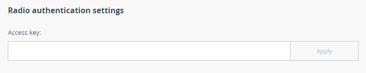
Radio authentication settings
An access key is required for mutual authorization of devices during a wireless connection establishing. Must be up to 64 characters long, without spaces and must be the same at both ends of the link.
Radio
The section includes the radio subsystem parameters necessary for wireless link establishing.
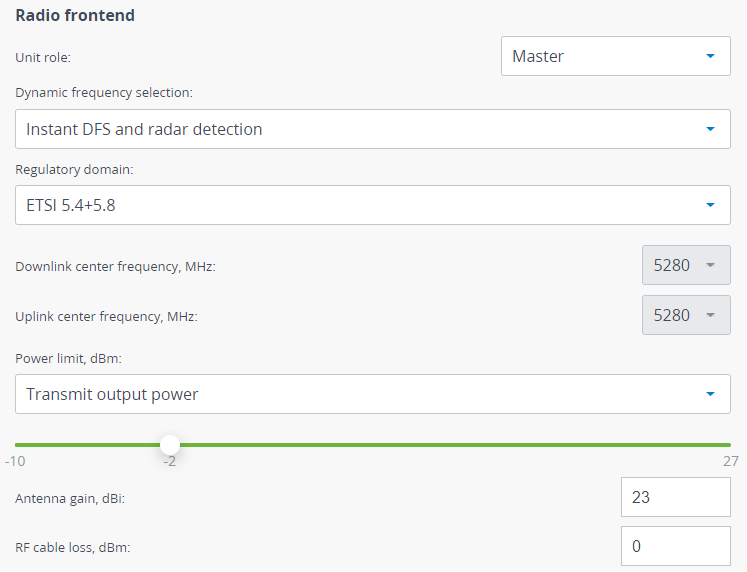
Radio frontend
Firstly select the Role of the device, one of the link devices should have the "Slave" role, the second - "Master".
The operating frequency can be selected manually or automatically, using the proprietary Instant DFS technology (only for the Quanta 5 family devices):
- Frequency selection off - the center frequency must be selected manually.
- Mandatory DFS and radar detction - the least noisy frequency will be selected in accordance with the set frequency grid. The device will block the frequency in case it detects a radar.
- Instant DFS - the least noisy frequency will be selected in accordance with the set frequency grid. The device will change frequency in case the strong interference appears.
- Instant DFS and radar detction - the least noisy frequency will be selected in accordance with the set frequency grid. The device will change frequency in case the strong interference appears and block the frequency in case it detects a radar.
For Instant DFS proper operation, make sure the Regulatory Domain is selected in accordance with the restrictions of your region. Each regulatory domain may limits the following parameters:
- Range of available center frequencies.
- Requirement of use LBT (Listen Before Talk) technique.
- Maximum EIRP (Equivalent Isotropically Radiated Power) value.
- Requirement of use radar detection technique.
The center frequency manual configuration is available only when automatic frequency selection is disabled.
- For the Master device downlink and uplink frequencies are available to configure. If values are the same, the device will use the TDD duplex mode, in case of different downlink and uplink streams values, the device will switch to the H-FDD duplex mode.
- For the Slave device, only the downlink frequency should be set.
To comply with regulatory requirements, the transmitter Power Limitation is often required. Two ways of power limiting are available:
- Transmitter power output - limits transmitter power to a specified value.
- EIRP - limits the overall system transmitted power, calculated by the formula: transmitter power + antenna gain - RF cable loss (gain and loss should be set in the fields below).
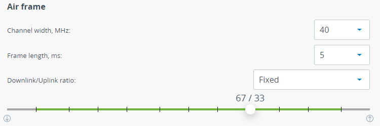
Air frame
Channel width must be the same at both sides of the link. Available values: 3.5, 5, 7, 10, 14, 15, 20, 28, 30, 40, 50, 56 MHz.
A frame length should be selected in accordance with traffic prevailing in the network. The greater frame length the more payload will be transmitted in one frame, but the latency will increase too. The lower frame length the less payload will be transmitted in one frame, but latency will decrease. Available values: 1, 2, 5, 10 ms. An automatic frame length selection is possible for the Master device.
A Downlink/Uplink ratio configuration is available on the Master device. In automatic mode, the ratio changes dynamically in accordance with the transmitted traffic. Manual mode allows to set a fixed value using the slider. Values available in fixed mode depend from channel width and frame length parameters.
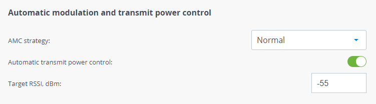
Automatic modulation and transmit power control
AMC strategy - allows to select a strategy of modulation switching for cases when the transmission medium conditions change. The following strategies are available:
- Normal - represents a balance between the error rate and throughput values.
- Conservative - assumes using higher CINR thresholds in order to minimize the error rate.
- Agressive - lowers the thresholds in order to use higher modulation levels and thus increase the throughput but also increase the error rate.
- Extreme - lowers the CINR threshold below the Aggressive strategy values in order to maximize selected modulation and throughput.
To optimize the energy of communication systems the Automatic transmit power control tool can be used, which allows to controls transmitter output power automatically based on target RSSI value. If actual RSSI level is lower then unit increases transmitter output power of the remote unit and vice versa. ATPC could not set value that may exceed the "Power limit" value.
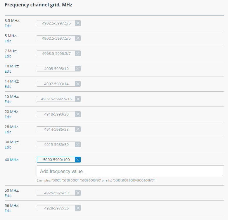
Frequency channel grid
Frequency channel grid should be configured for each channel width. The frequency grid allows to limit the scan range in case the center frequency is automatically selected. Also Instant DFS will use these restrictions when monitoring the noise situation. Narrow grid of available frequencies speeds up scanning and link establishing process. Manual center frequency selection will also be limited to the values indicated in the grid.
Network
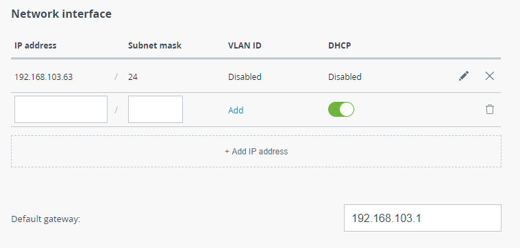
This section allows to assign an IP address or several addresses to the wired interface, the default gateway value can also be specified.
Network interface
Click the "Add IP address" button to add a new address. There are two ways to assign an IP address:
- Automatically - the IP address will be obtained automatically from the DHCP server.
- Manual - the IP address and netmask are specified manually.
In order to restrict access to device management to the selected VLANs, assign the required VLAN ID to the management IP address in the range from 1 to 4096. Without enabled VLAN-based switching such configuration will limit only access to the device, all other traffic will be transmitted unchanged.
Use the Default gateway field to configure the IP address of the default router.
Switch
Network ports
Each Quanta 5 / Quanta 6 family device has 3 ports:
- ge0 - combo port, depends on physical connection type can be Gigabit Ethernet 1000BASE-T or SFP Port 1000BASE-X (to specify the connection type see "Wired interface" section on the Dashboard);
- radio - internal radio interface;
- mgmt - internal interface for device management.
Only ge0 interface is available to configure in this section. The following parameters can be changed:
- Status: enabled/disabled.
- Duplex: duplex mode, "auto" is by default. We recommend setting the autonegotiation mode provided by the Ethernet standard. The problem can occur while connecting two devices with different duplex settings. For example, if one device has the autonegotiation mode, and the other - fixed full duplex mode.
- Description: arbitrary text description.

QoS
Enable/disable prioritization strategy. Unit will recognize the 802.1p tags in Ethernet frame headers. Based on these tags priorities will be autlomatically assigned to the frames when they are sent over the radio interface. After transmission over radio interface frames with tags are sent to Ethernet. Priorities may be adjusted manually if a VLAN based switching is enabled.
VLAN based switching
VLAN based switching allows to create list of allowed VLANs and their handling on the unit switch plane. If VLAN based switching is enabled but no VLANs are added, device ports will allow untagged traffic only. Each entry of list establishes the relationship between VLAN ID and ports VLAN modes. "VLAN 1" is created by default and could not be deleted, it's enough to set all interfaces to "off" mode to disable it.
VLAN ID - VLAN tag in range from 1 to 4096. May be set in a few ways, examples:
- 12
- 10-20
- 100,200,300
- 23,24,25,50-100
Description - arbitrary text description.
Priority - allows to set the priority of a specific VLAN according to 802.1p ranging from 0 to 7, where 0 - the lowest priority level, 7 - the highest. QoS support should be enabled.
Port mode determines the way which VLAN tagged network packets will be handled by switch on each port. There are three ports modes:
- Off - denies all traffic of a specified VLAN. If none of the modes is selected, the port will be marked as "Off".
- A - access mode. Operates as access port, allows only untagged traffic.
- T - tagged mode. Operates as trunk port, allows tagged traffic of a specific VLAN to pass through this port
- U - untagged mode. Operates as trunk port, allows untagged traffic of a specific VLAN to pass through this port.
Configuration Example
Scenario 1
There is a link established between the data center and client devices using Quanta 5 devices. User traffic for each subscriber is isolated using VLAN tags. Devices are accessible only in VLAN 10, and the Slave device management is possible only from the data center through the radio link. For subscriber 1 traffic is transmitted in VLAN 20, for subscriber 2 - in VLAN 30. Subscriber 2 traffic must have the highest priority.

Switching will be configured in the following way:
- For Master device:
- All ports are configured in "Tagged" mode for VLAN 10.
- For VLAN 20, the "ge0" and "radio" ports are configured to a "Tagged" mode, the "mgmt" port is off to restrict an access to the device.
- For VLAN 30, the "ge0" and "radio" ports are configured to a "Tagged" mode, the "mgmt" port is off to restrict an access to the device. This VLAN has the highest priority (7).
- For VLAN 1, all ports are off as the other traffic must be dropped.
- For Slave device:
- The "mgmt" and "radio" ports are configured in "Tagged" mode for VLAN 10, the "ge0" port is off to restrict an access to the device via wired network segment.
- For VLAN 20, the "ge0" and "radio" ports are configured to a "Tagged" mode, the "mgmt" port is off to restrict an access to the device.
- For VLAN 30, the "ge0" and "radio" ports are configured to a "Tagged" mode, the "mgmt" port is off to restrict an access to the device. This VLAN has the highest priority (7).
- For VLAN 1, all ports are off as the other traffic must be dropped.

Scenario 2
Net 1 and Net 2 are connected by a radio link between two Quanta 5 devices. In Network 1 all traffic is tagged with VLAN 20, in Network 2 - VLAN 30. The VLAN tags are changed by Quanta 5 devices.

Switching will be configured in the following way:
- For Master device: port "ge0" for VLAN 20 is set to "Tagged" mode, "radio" port is set to "Untagged" mode. Since the manipulations with VLAN tags are applied at the output of the interface, traffic in this VLAN will be transmitted through the radio untagged.
- For Slave device: port "ge0" for VLAN 30 is set to "Tagged" mode, "radio" port is set to "Untagged" mode. Untagged traffic is received over the radio interface and is tagged with VLAN 30 when transmitted over the wired interface.

Connectivity matrix
Allows to configure the traffic transfer between the network ports of the device. Configuration is performed visually using switches. The green switch indicates allowed connections, the red one - denied:
- ge0 - Gigabit Ethernet port.
- radio - internal radio interface;
- mgmt - internal interface for device management.
To restrict access to the device from the wired segment, it is enough to break the connectivity between the "ge0" and "mgmt" interfaces.
Traffic flow between ports is performed in accordance with VLAN modes set, if the VLAN based switching is enabled.

SNMP
SNMP allows the administrator to gather information about key device parameters and wireless links, including information about changes. The use of any monitoring system helps to timely receive information about the network infrastructure state using Infinet devices. Currently, the Quanta 5 / Quanta 6 devices families support SNMP protocol versions v1 v2c and v3.
The SNMP Protocol has two branches, the agent and the management stations:
- The agent sends data to the management station. Monitoring system - provides data gathering from all agents in the network.
- The monitoring system receives and processes events.
- The information is passed through requests and replies with the use of the MIB.
- The management station or monitoring system is responsible for decoding the SNMP packets and providing an interface to the administrator.
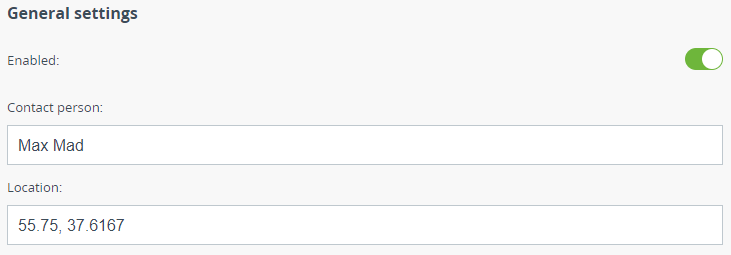
General settings
This section allows to enable/disable SNMP protocol support.
To make the device identifying easier, enter the data of Contact person performing the maintenance. The physical location of the device can also be specified in an arbitrary format, the line length should not exceed 20 characters.
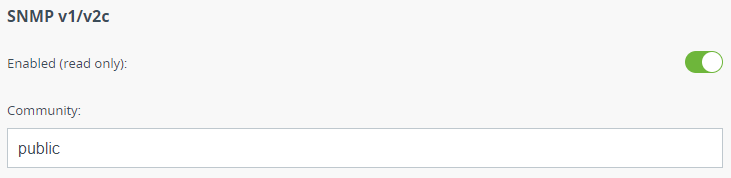
SNMP v1/v2c
This section allows to enable/disable the SNMP v.1 and v.2c support. The first version of the SNMP protocol lacks security, that hinders its use for network management, so SNMP v.1 and v.2c operates in read-only mode. Enabled by default.
Set the Community name for read-only mode of SNMP v.1 and v.2c, by default: "public". The community name passes along with the data packet in clear text.
Due to the security level of SNMP v.3 is higher than of SNMP v.1 and v.2c, it allows not only the data collection but also to manage devices. Detailed information about the devices management via the monitoring system is available in the corresponding article of the technical documentation.
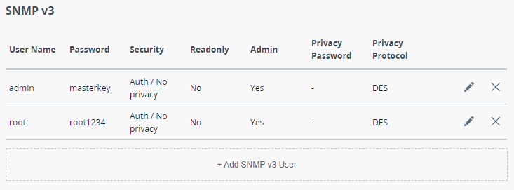
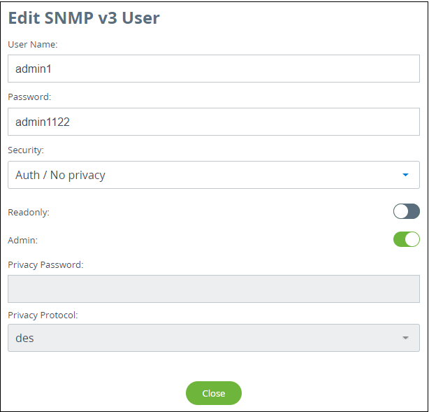
Add SNMP v3 User. In the appeared window, enter the User Name, select the required Security level:
- "No auth / No privacy" – the lowest security level without authentication and privacy, only User Name needs to be set. This level of protection does not allow management via the monitoring system.
- "Auth / No privacy" – middle level with authentication but without privacy, User Name and Password are required.
- "Auth / Privacy" – highest level with authentication and privacy, User Name, Password, Privacy Password and Privacy Protocol should be set.
Configure permissions for this entry. To collect data without the possibility of making changes, activate the Read Only mode, to implement all management possibilities, activate the Admin mode.
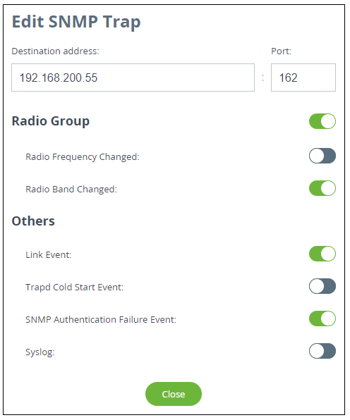
SNMP traps
The devices polling cycle of the monitoring system is 5 minutes. To speed up the process of detecting incidents on devices, SNMP traps can be send each time an incident occurs, regardless of the polling process.
Enable SNMP traps by activating the corresponding flag. Set the source IP address to help the monitoring system to identify the device. Create a new entry by clicking the "Add SNMP Trap" button.
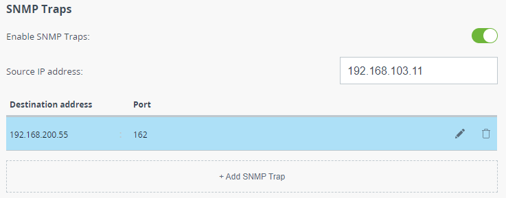
In the appeared window, set the destination IP address, for example, the monitoring system, and UDP port (usually 162 is used). Activate the checkboxes opposite the groups of traps that should be sent by the device.